EasyManua.ls Logo

Ampac EV3000 - WIP;EAID Extension Connections

Ampac EV3000
54 pages
Print Icon
To Next Page IconTo Next Page
To Previous Page IconTo Previous Page
Loading...
Page 27
EV3000
INSTALLATION & COMMISSIONING
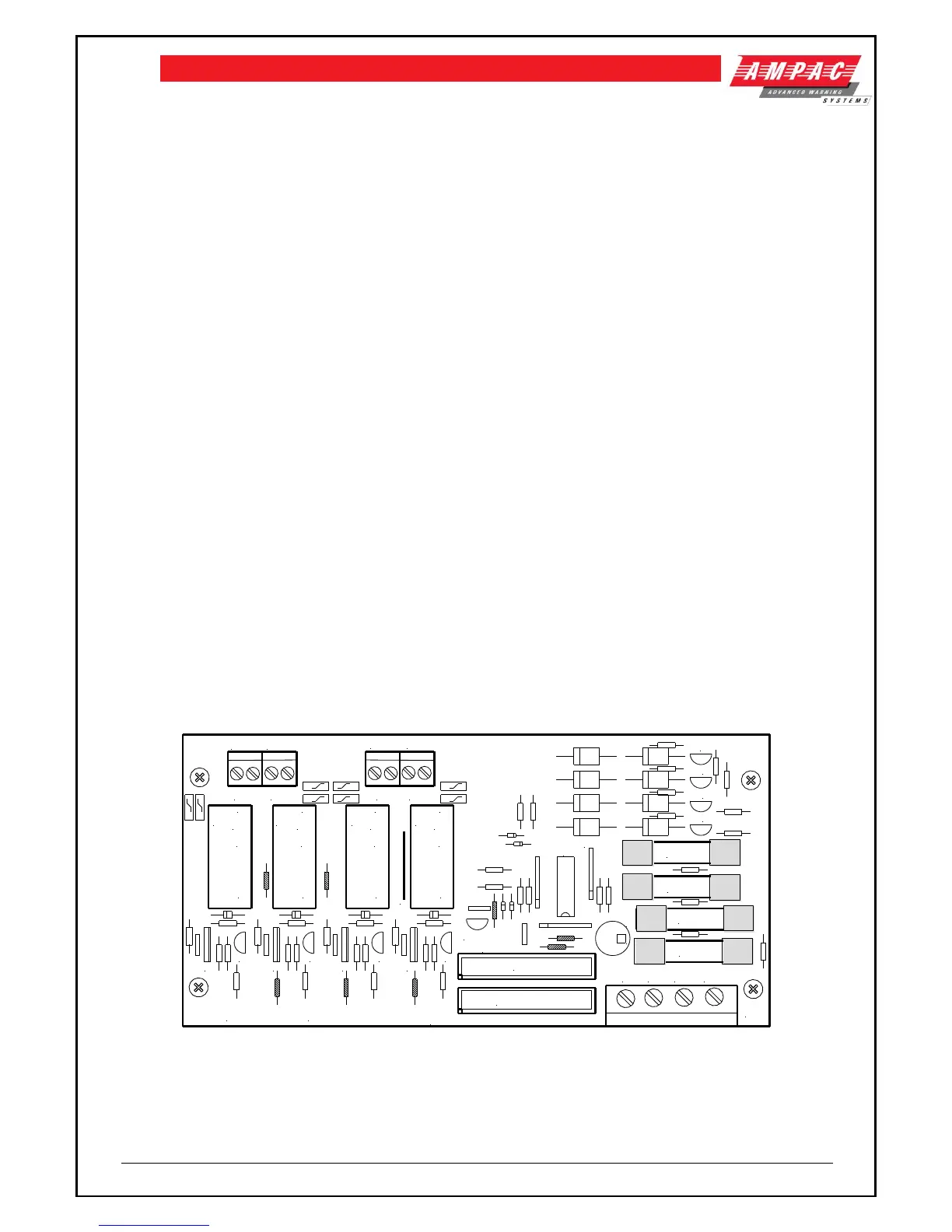
10.5 Visual Indicators Output Connections
The 302-623B / 302-623C or the BRDEV3VOB3-A / BRDEV3VOB3-B are the field connection
boards for the visual indicators. Each board will terminate four (4) zones of visual indicators.
Each zone output can cater for up to:
40 pair LED strobes.
16 pair XENON strobes.
The EV3000 visuals operate with a two-core cable to a pair of visual indicators, i.e. Alert (Amber),
Evac (Red). Visuals are connected in reverse polarity to each other (See Figures 27 and 28).
NOTE: Circuit to visual indicators are polarised refer to section 11.2 for more detail.
10.5.1 Connections
Field Connections
Use
TB1 - 1, 2
Output Pair Zone 1
TB2 - 1, 2
Output Pair Zone 2
TB3 - 1, 2
Output Pair Zone 3
TB4 - 1, 2
Output Pair Zone 4
Factory Connections
Use
TB5-1,2
+24V
TB5-1,2
0V
CN1
Control Cable to 302 4220 board.
CN2
Control Cable to next 302-623B/C board or
BRDEV3VOB*-A/B
10.5.2 Fusing
302-623B / C
Fuse
Use
Rating
F1 - 4
+24V Output 1 - 4
3 amp 3AG
BRDEV3VOB*-A /B
Fuse
Use
Rating
F1 - 4
+24V Output 1 -4
3 amp M0205
27V27V0V0V
O/P1
O/P2
O/P3 O/P4
VISUAL OUTPUT BOARD
302 6230B / C
TO MAF
TB5
+
+
Q10
Q7
Q1
Q4
IC1
Q2
RL1
///
N/C
C
N/O
RL2
///
N/C
C
N/O
F1 3A
CN1
CN2
Q3
TB1
TB2
TB3
TB4
RL3
N/O
C
N/C
///
RL4
N/O
C
N/C
///
Q6
Q5 Q8
Q9 Q12
Q11
LINK
IC2
SIL3
F2 3A
F3 3A
F4 3A
TO NEXT 302-6230
Figure 23: 302-623B Visual Output Board (XENON STROBES) /
302-623C Visual Output Board (LED STROBES)

Table of Contents

Other manuals for Ampac EV3000

Related product manuals