Connections and Wiring
16
NI-3101-SIG Signature Series NetLinx Integrated Controller
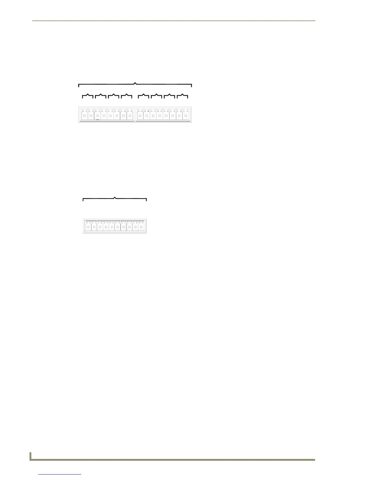
Relay connections
Use A for common and B for output (FIG. 8). Each relay is isolated and normally open. A metal
connector strip is also provided to common multiple relays.
Input/Output (I/O) Port: Connections and Wiring
The I/O port responds to either switch closures or voltage level (high/low) changes, or it can be used for
logic-level outputs.
Up to eight devices may be connected to the I/O connectors on the NI-3101-SIG (FIG. 9). A contact
closure between the GND and an I/O port is detected as a Push.
When used for voltage inputs, the I/O port detects a low signal (0 - 1.5 VDC) as a Push, and a
high signal (3.5 - 5 VDC) as a Release (this IO port uses 5V logic but can handle up to 12V
without harm).
When used for outputs, the I/O port acts as a switch to GND and is rated for
200 mA @ 12 VDC. This device can use up to 8 I/O ports.
The PWR pin provides +12 VDC @ 200 mA and is designed as a power output for the PCS
Power Current Sensors, VSS2 Video Sync Sensors (or equivalent).
The GND connector is a common ground and is shared by all I/O ports. A common ground is
shared with I/O ports 1 - 8.
FIG. 8 RELAY connector (male) NI-3101-SIG
FIG. 9 INPUT/OUTPUT connector (male)
RELAYS (Port 8)
B
6
A
8
B BB
7
A
5
BAA
4
BA
A
3
A
2
B
1
AB
NI-3101-SIG relay connector
configuration (Port 8)
I / O (Port 17)
4
+12V
78 65
GND
2
3
1
NI-3101-SIG I/O connector
configuration (Port 17)
 Loading...


