Contents qTOWER
3
touch/qTOWER
3
G touch
4
Figures
Fig. 1 Layout of the qTOWER³ touch .......................................................................... 15
Fig. 2 Schematic structure of the Epi fluorescence photometer ............................... 16
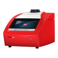
Fig. 3 qTOWER³ touch front view ............................................................................... 18
Fig. 4 Connections and control elements (right-side) ............................................... 19
Fig. 5 qTOWER³ touch, open ....................................................................................... 19
Fig. 6 qTOWER³ touch rear view ................................................................................. 20
Fig. 7 Type plate........................................................................................................... 20
Fig. 8 Voltage selector switch on the bottom of the qTOWER³ touch ...................... 21
Fig. 9 Mains cable ........................................................................................................ 21
Fig. 10 Start screen of qPCRsoft touch ..................................................................... 23
Fig. 11 Position of additional vessels for measurements with few samples ......... 25
Fig. 12 Position A1 on the sample block .................................................................. 25
Fig. 13 Fuse holder on the rear of the device .......................................................... 28
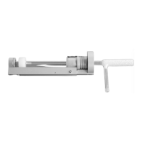
Fig. 14 Transport lock in the qTOWER
3
touch .......................................................... 35