EasyManua.ls Logo

Andor Technology Zyla sCMOS 4.2 PLUS User Manual

Andor Technology Zyla sCMOS 4.2 PLUS
78 pages
To Next Page IconTo Next Page
Page #1 background imageLoading...
Page #1 background image
8.2 x 8.2 mm / 512 x 512 sensor
Lowest Noise Imaging EMCCD
Version 2.0 rev 18 Feb 2021
Hardware Guide
Covers Zyla 4.2 PLUS and 5.5 models with
Camera Link or USB 3 connections and
air or water cooling
andor.com
© Andor Technology 2021
Zyla sCMOS

Table of Contents

Question and Answer IconNeed help?

Do you have a question about the Andor Technology Zyla sCMOS 4.2 PLUS and is the answer not in the manual?

Andor Technology Zyla sCMOS 4.2 PLUS Specifications

General IconGeneral
BrandAndor Technology
ModelZyla sCMOS 4.2 PLUS
CategoryMeasuring Instruments
LanguageEnglish

Summary

SECTION 1: INTRODUCTION

Help and Technical Support

Contact information for user assistance and technical queries.

Components and Connections

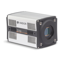
Details of standard and optional accessories, and power/signal connections.

SECTION 2: FEATURES AND FUNCTIONALITY

sCMOS Structure and Operation

Explanation of the sCMOS sensor architecture and its operational principles.

Rolling and Global Shutter

Comparison and functionality of rolling and global shutter modes.

Sensor Readout Optimization

Options for optimizing sensor readout including gain and pixel rates.

SECTION 3: INSTALLATION

Safety Considerations

Essential safety precautions to be followed before commencing installation.

Camera Mounting

Secure methods for mounting the camera to prevent damage or injury.

SECTION 4: OPERATION

Connecting Your Camera and Switching it on

Step-by-step guide for connecting the camera and powering the system on.

Using the Lens Mount Adaptors

Instructions for attaching and adjusting C-mount, CS-mount, and F-mount adaptors.

SECTION 5: MAINTENANCE

Regular Checks

Routine checks for the External Power Supply and mains cable integrity.

Fuse Replacement

Guidelines for replacing the integrated fuse in the mains cable.

SECTION 6: TROUBLESHOOTING

Camera is not recognized by PC

Steps to diagnose and resolve issues with PC camera recognition.

Camera does not cool to the required temperature

Troubleshooting steps for when the camera fails to reach the target temperature.

SAFETY AND WARNING INFORMATION

Handling Electrostatic Sensitive Devices

Precautions for handling components sensitive to electrostatic discharge.

Regulatory Compliance

Information regarding compliance with EU EMC and LV Directives.

Revision History

Updates to the Manual

Information on manual updates and how to obtain new versions.

1.4 Components

1.4.1 Accessories

List of optional and additional accessories available for the Zyla camera.

1.5 Power And Signal Connections

1.5.1 Power Supply Unit (PSU)

Details on the external 12V DC power supply unit and its connection.

1.5.2 Connectors

1.5.3 Multi I/O Timing Cable Pin Outs

Pinout details for the 15-way D type multi I/O timing cable connector.

1.5.4 Impedance Information

1.5.5 Other Connections

Description of CL1, CL2, USB 3.0, and Power connector types.

1.6 Cooling Hose Connectors (Water Cooled Models only)

1.6.1 Important Considerations when using Cooling Systems

Key considerations for using water cooling systems with the camera.

2.1 sCMOS Structure and Operation

SCMOS Sensor Architecture

Diagram and explanation of the sCMOS sensor's pixel structure and operation.

2.2 Rolling and Global Shutter

2.2.1 Rolling Shutter

Detailed explanation of the rolling shutter mechanism and its characteristics.

2.2.2 Global Shutter (Zyla 5.5 only)

Explanation of the global shutter mechanism and its trade-offs.

2.3 Understanding Read Noise in sCMOS

Representative Read Noise Histogram

Histogram showing read noise distribution compared to Interline CCD.

2.3.1 Spurious Noise Filter

Spurious Noise Filter Demonstration

Visual demonstration of the spurious noise filter's effect on images.

2.3.2 Blemish Correction

Types of Blemishes

Identification and compensation for hot pixels, noisy pixels, and unresponsive pixels.

2.4 Dual Amplifier Dynamic Range

Amplifier and ADC Block Diagram

Block diagram illustrating the dual amplifier and ADC architecture.

2.5 Sensor Readout Optimization

2.5.1 Gain Channel Control

Explanation of choosing between 12-bit gain channels or 16-bit setting.

2.5.2 Pixel Readout Rate

Details on pixel readout rates and their impact on frame rates and noise.

2.6 Trigger Modes

Internal Trigger

Camera determines exposure time based on acquisition settings.

External Trigger

Camera accepts triggers from an external source via I/O connector.

Software Trigger

Camera reacts to trigger events issued via software.

2.6.2 Rolling Shutter Triggering Modes

Rolling Shutter Signals Overview

Explanation of TTL outputs like FIRE, FIRE n, FIRE ALL, and FIRE ANY.

2.6.2.1 Timing Parameters and Ext Triggering for Zyla 5.5

2.6.2.2 Timing Parameters and Ext Triggering for Zyla 4.2

Timing parameters for Zyla 4.2 in external triggering modes.

2.6.2.3 Rolling Shutter Internal Triggering (Non-Overlap Mode)

Figure 16: Rolling Shutter Internal Triggering

Diagram illustrating internal triggering sequence for non-overlap mode.

2.6.2.4 Rolling Shutter Internal Triggering (Overlap Mode)

Short Exposures Timing Parameters

Timing parameters for overlap mode with short exposures.

2.6.2.5 Rolling Shutter External / Software Triggering (Non Overlap Mode)

Figure 19: Rolling Shutter External/Software Triggering (Non Overlap Mode)

Diagram for external/software triggering in non-overlap mode.

2.6.2.6 Rolling Shutter External Exposure Triggering (Non-Overlap Mode)

Table 16: Timing Parameters

Timing parameters for external exposure triggering in non-overlap mode.

2.6.2.7 Rolling Shutter External Exposure Triggering (Overlap Mode)

Table 17: Timing Parameters

Timing parameters for external exposure triggering in overlap mode.

2.6.2.8 Rolling Shutter External Start Triggering

Figure 22: Rolling Shutter External Start Triggering (Non Overlap)

Diagram for external start triggering in non-overlap mode.

2.6.2.9 Rolling Shutter Global Clear Internal (Non-Overlap Mode)- Zyla 4.2 only

Table 18: Timing Parameters

Timing parameters for global clear internal triggering on Zyla 4.2.

2.6.2.10 Rolling Shutter Global Clear External/Software Triggering (Non-Overlap Mode) - Zyla 4.2 Only

Figure 24: Timing Parameters

Diagram for global clear external/software triggering on Zyla 4.2.

2.6.2.11 Rolling Shutter Global Clear External Exposure Triggering (Non-Overlap Mode) - Zyla 4.2 Only

Table 20: Timing Parameters

Timing parameters for global clear external exposure triggering on Zyla 4.2.

2.6.2.12 Rolling Shutter Triggering Constraints

Table 21: Rolling Shutter Mode Triggering Constraints

Summary of constraints for various rolling shutter triggering modes.

2.6.3 Global Shutter Triggering Modes (Zyla 5.5 only)

Table 22: Timing Parameters

Timing parameters based on sensor clock speed for global shutter modes.

2.6.3.1 Global Shutter Internal Triggering (Non-Overlap Mode)

Figure 26: Global Shutter Internal Triggering - Short Exposures

Diagram for global shutter internal triggering in non-overlap mode (short exposures).

2.6.3.2 Global Shutter Internal Triggering (Overlap Mode)

Table 25: Timing Parameters

Timing parameters for global shutter internal triggering in overlap mode.

2.6.3.3 Global Shutter External/Software Triggering

Figure 29: Global Shutter External/Software Triggering (Non Overlap Mode)

Diagram for global shutter external/software triggering (non-overlap mode).

Table 26: Global Shutter External/Software Triggering Timing Parameters (Non Overlap Mode)

Table 27: Global Shutter External/Software Triggering Timing Parameters (Overlap On)

Timing parameters for global shutter external/software triggering (overlap mode).

2.6.3.4 Global Shutter External Exposure Triggering (Non-Overlap Mode)

Table 28: Timing Parameters

Timing parameters for global shutter external exposure triggering (non-overlap mode).

2.6.3.5 Global Shutter External Exposure Triggering (Overlap Mode)

Figure 32: Global Shutter External Exposure Triggering (Overlap Mode)

Diagram for global shutter external exposure triggering (overlap mode).

2.6.3.6 Global Shutter External Start Triggering

Table 30: Timing Parameters (Overlap Off)

Timing parameters for global shutter external start triggering (overlap off).

2.6.3.7 Global Shutter Triggering Constraints

Table 32: Global Shutter Mode Triggering Constraints

Summary of constraints for various global shutter triggering modes.

2.7 ACQUISITION MODES

Single Scan

Acquires a single frame upon receiving a valid trigger.

Kinetic Series

Acquires a finite, user-defined number of frames.

Accumulate

Accumulates multiple frames into a single image.

2.7.4 Run Till Abort Acquisition

2.7.4.1 Live Mode

Acquires frames continuously with minimum latency until aborted.

2.7.5 Fast Exposure Switch

Allows changing exposure time during acquisition.

2.7.7 LightScan PLUS

Functionality for enhanced rolling shutter scanning control.

2.7.7.1 Multiple Readout Directions

2.7.7.2 FlexiScan

Optimizes scanning speed and exposure for confocality and signal strength.

3.3 Coolant Hose Connection and Disconnection (Water Cooled Models)

3.3.1 Coolant Recommendations

Recommendations for coolant type, temperature, flow rate, and pressure.

3.3.2 Connecting the Coolant Hoses

3.3.3 Disconnecting the Coolant Hoses

Procedure for safely connecting and disconnecting coolant hoses.

3.4 Recommended Computer Requirements

Hard Drive Requirements

Specifications for hard drive write speed and PCI Express slots.

3.5 Installing Software (Solis or SDK3)

Selecting the Camera Type

Guide on selecting the correct camera type during software installation.

3.6 Installing the Camera Framegrabber Card

Figure 37: Installing the FrameGrabber PCIe card

Illustrations showing PCIe card installation for Camera Link and USB 3.0 models.

3.7 Checking & Setting BIOS options (for PCs not supplied by Andor)

BIOS Options to Check/Set

Specific BIOS settings like C-States and Speed-step to configure.

3.8 Software Support

Andor SDK3 Documentation

Information on accessing and using the Andor SDK3 documentation.

SECTION 4: OPERATION

4.1 Connecting your Camera and Switching it on

Procedure for connecting the camera to the PC and powering on the system.

Figure 38: Zyla Port Connections

Diagrams showing Camera Link and USB 3.0 port connections.

4.2 Using the Lens Mount Adaptors

4.2.1 C-mount Adaptor

Instructions for adjusting and locking the C-mount adaptor.

4.2.2 CS-mount Adaptor

Figure 41: CS-mount adaptor

Illustration of the CS-mount adaptor and its locking screws.

4.2.3 F-mount Adaptor

Figure 42: F-mount adaptor

Illustration of the F-mount adaptor and its locking collar.

4.3 Cooling

4.3.1 Integral Thermal Protection

Measures to prevent camera overheating and system failure.

4.3.2 TE Cooling (Air-Cooled Models)

Explanation of thermoelectric cooling for air-cooled camera models.

4.3.3 TE Cooling (Water Cooled Models)

Benefits of thermoelectric cooling for water-cooled camera models.

4.4 Emergency Mains Disconnection

WARNING: SWITCH OFF THE POWER

Critical warning for emergency power disconnection procedures.

5.4 Zyla Chamber Design And Service Guidance

Moisture Ingress and Desiccant Saturation

Understanding moisture ingress and desiccant saturation in the sensor chamber.

5.5 Cooling Hoses and Connections

Checking Coolant Hoses

Routine checks for coolant hose leakage, damage, or wear.

6.4 Fan not operating as expected

Fan Speed Control

Information on fan speed behavior based on heat sink temperature.

6.6 Fire, Aux_Out and Arm outputs not functioning correctly

6.7 External Trigger input not functioning correctly

Troubleshooting for external trigger input and TTL output functionality.

6.8 Condensation Appearing On Exterior Of Camera (Water Cooled Model)

Preventing Condensation

Actions to take if condensation appears on the camera exterior.

6.9 Condensation Effect Noticeable in Images

Sensor Chamber Service

Guidance on sensor chamber service to address moisture ingress issues.

APPENDIX A: SPECIFICATIONS

Model Specific Specifications

Technical specifications differentiating Zyla 5.5 and Zyla 4.2 PLUS models.

General Specifications

Mechanical Specifications

Physical dimensions, weight, and cooling vent clearance details.

Environmental Specifications

Operating temperature, humidity, pollution degree, and EMC compatibility.

External Power Supply Requirements

Camera Power Specifications

Details on mains input, power consumption, voltage, and current ratings.

APPENDIX B: MECHANICAL DRAWINGS

Zyla Mechanical Drawings

Detailed mechanical drawings of the Zyla camera, including mounting points.

Air Cooled Models

Mechanical drawings specific to the air-cooled camera models.

APPENDIX C: DEW POINT GRAPH

Understanding Dew Point

Graph showing relationship between humidity, temperature, and dew point.

APPENDIX D: OTHER INFORMATION

D.1 Terms and Conditions of Sale and Warranty Information

Information on sales terms, conditions, and warranty provisions.

D.2 Waste Electronic and Electrical Equipment Regulations 2006 (WEEE)

Company statement regarding the disposal of Waste Electronic and Electrical Equipment.

Related product manuals