version 2.0 rev 18 Feb 2021
13
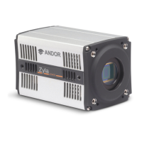
1.5.2 Connectors
Figure 3: ZylaBackPlateConnections(Left)Cameralinkversions(Right)USB3.0
version
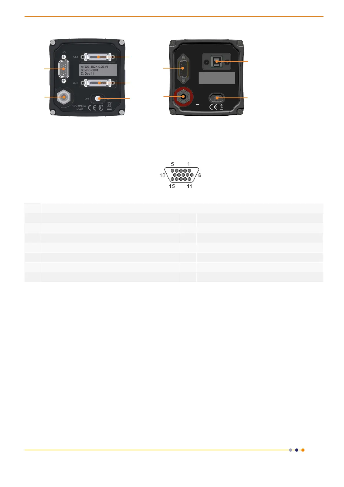
1.5.3 Multi I/O Timing Cable Pin Outs
Table 2: Multi I/O Timing Cable Pinouts 15-way D type connector
1 ARM 9 Reserved
2 AUX_OUT_1 10 Reserved
3 FIRE n 11 Reserved
4 FIRE 12 Reserved
5 AUX_OUT_2 13 Reserved
6 Ground 14 Reserved
7 External Trigger 15 Reserved
8 Spare (I)
• External Trigger and Spare input are 5V TTL input. By default they trigger on a rising edge.
• Fire, Fire n, Arm, AUX_OUT_1 and AUX_OUT_2 outputs are all TTL timing outputs (please also refer to
Section 1.6.4 for information on impedance matching)
• TTL I/O can be individually inverted via software (e.g. Solis or SDK)
• Pins 9 to 15 are reserved and should not be used.
• AUX_OUT_1 supplies the ‘FIRE ALL’ output by default. This is the logical AND of the FIRE pulses associated
with Row #1 and Row #n (the last row read out in the image frame). Therefore the FIRE ALL pulse
represents the time within a frame when all rows on the sensor are simultaneously exposing.
AUX_OUT_1isalsocongurableasFIRE,FIREnandFIREANY.TheFIRE ANY pulse represents the time
within a frame when any row of the image frame is exposing. Refer to Section 2.6 for the behaviour of
thesesignalsandtotheSDK3manualforconguringtheAUX_OUT_1output.
NOTE: This congurable output is only available on cameras with FPGA version numbers ≥ 20120802
and Solis versions ≥ 4.22.30001.0 (SDK users require version ≥ 3.5.30001.0).
• AUX_OUT_2 output is reserved for future use.
• I/O Timing Interface cable (Andor part number ACC-ACZ-05612) gives access to all of the above I/O
functions (excluding Ground and Reserved).
12V 5A
Max
OFFON
I/O
USB
3.0
Made in UK
1
1
2
2
3
4
5
5
6
1. I/O 15-Way D Type
Connector
2. 12V DC Power
Connector
3. CL1 connector
4. CL2 connector (Not
present on 3-tap
version)
5.On/OSwitch
6. USB 3.0 Connector
 Loading...