05/2008 Rev. 0.6
71
6.1 Electronics summary
WARNING
During repairs or maintenance work, avoid electrostatic
discharge (ESD) on the control unit.
● Control unit ........................................ 6.1.1
● Power supply 230Vac:24V 65W ........ 6.1.2
● Circuit board ...................................... 6.1.3
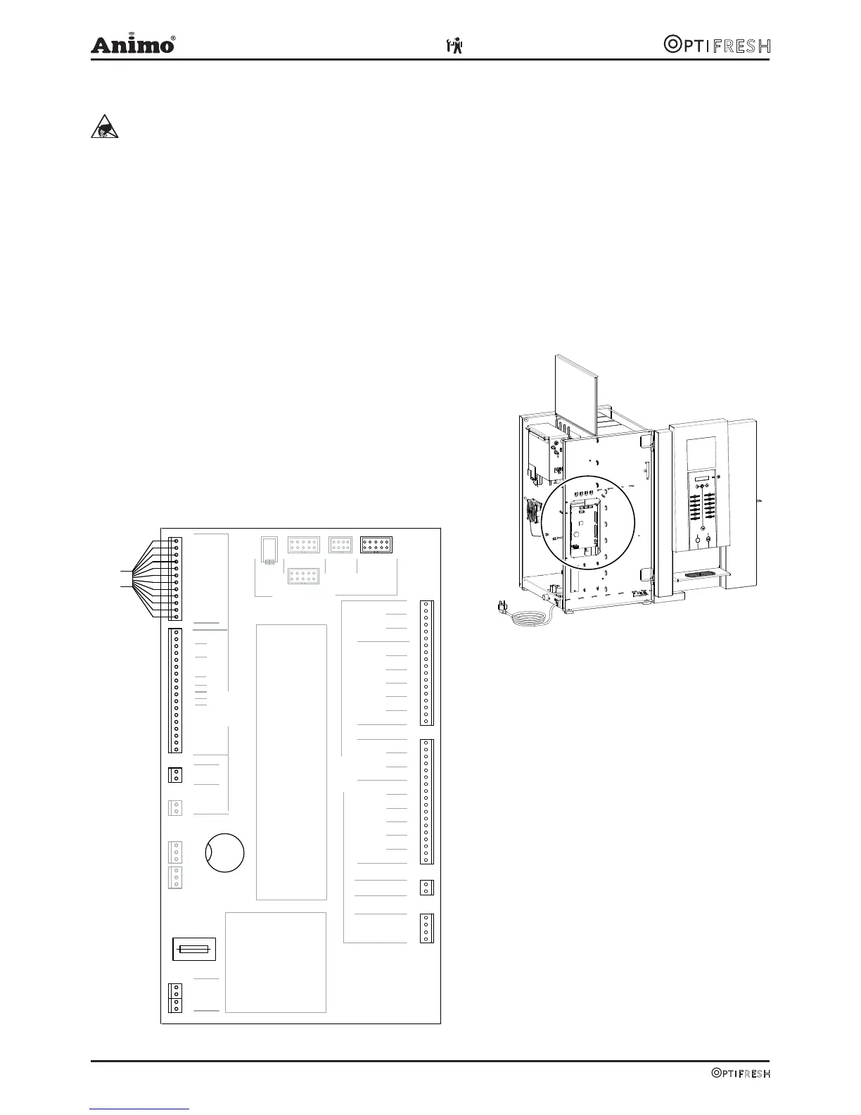
6.1.1 Control unit
This control unit is the device’s main control unit and
is accessible by removing the left side panel (fig. 16a).
The following important parts can be found in the main
control unit (fig. 16):
● Fuse (6, 3A t): to safeguard the power supply to the
control unit.
● Battery: to maintain the clock and counter function
when there is no power supply to the device.
18
17
16
15
14
13
12
11
10
9
8
7
6
5
4
3
2
1
MIX/BR
MIX2
MIX3
IM1
IM2
IM3
IM4
IM5
IM6
2
1
KW1
KW2
KW3
DV1
DV2
DV3
DV4
DV5
DV6
18
17
16
15
14
13
12
11
10
9
8
7
6
5
4
3
2
1
2
1
HEATER
RELAIS
DOSING VALVESVALVES
INGREDIENT MOTORSMIXERS
4
3
FAN
INLET
OUTPUTS
G13MDB
RS232
COMMUNICATION
POWER SUPPLY
MICROCONTROLLER
J15
J6
J2
USB
J4
2
1
TEMP1
2
1
4
3
24V DC
KEY / DISPLAY
INPUTS
J12
J7
J16
J1
F1
+
BATT
F6,3AT
1
2
3
4
5
6
7
8
9
10
11
12
18
17
16
15
14
13
12
11
10
9
8
7
6
5
4
3
2
1
SENSORS
+5V
LB
LSL
GND
AS
BS
DS
LSH
GND
GND
GND
GND
+24Vdc
CSI
Fig. 16
Fig. 16a