74
05/2008 Rev. 0.6
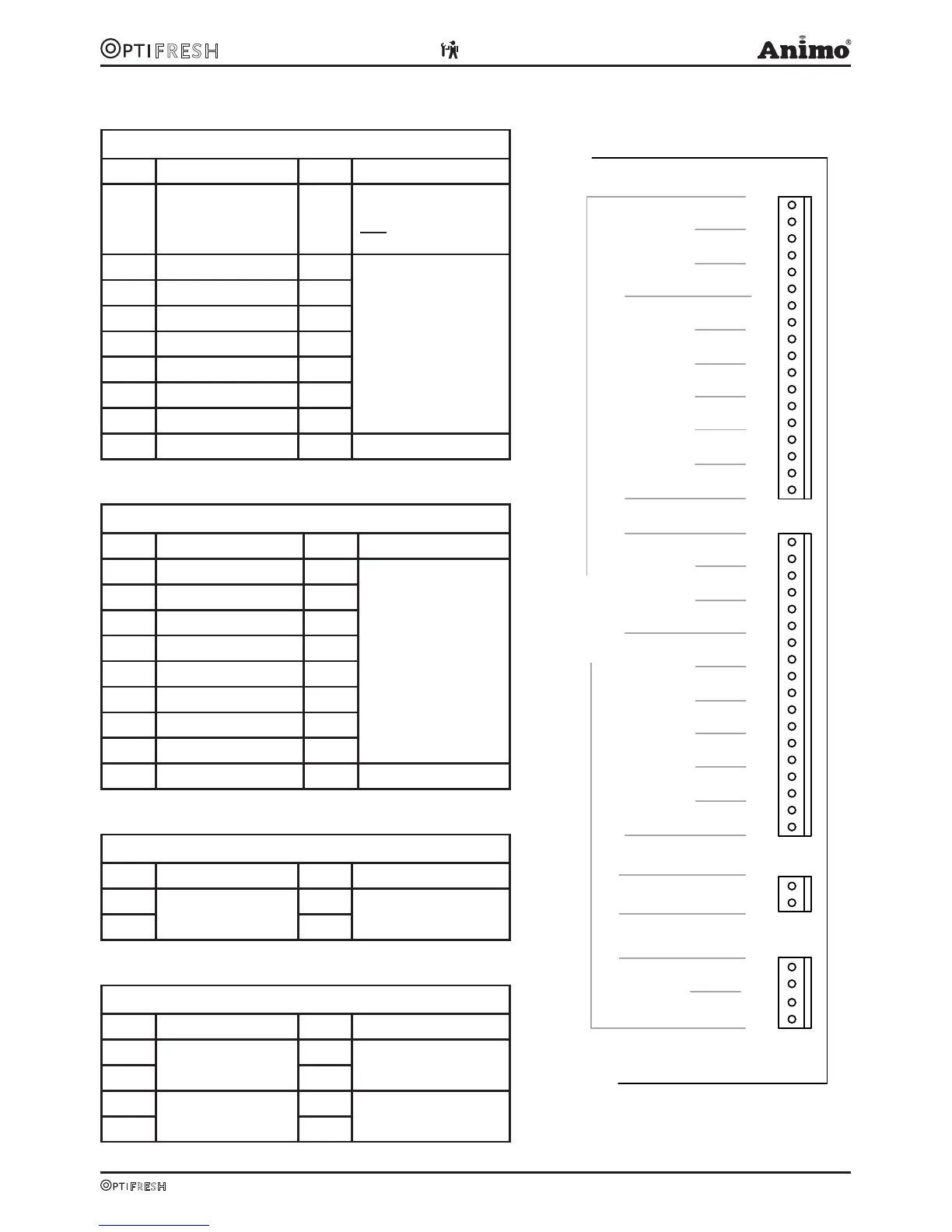
6.3 Main circuit board exits
Connector J2
Pin Motor Colour Comments
17-18 Brewer / Mixer 1
Black
Correct direction of rota-
tion = red wire (+24VDC)
NOT on red spot of the
Brewer Motor
15-16 Mixer 2 Violet
Take care to rotate in
the right direction!
Shared +24 DC (red wire)
on red spot on Mixer and
Ingredients Motor.
13-14 Mixer 3 Pink
11-12 Ingredient Motor 1 Brown
9-10 Ingredient Motor 2 Green
7-8 Ingredient Motor 3 White
5-6 Ingredient Motor 4 Yellow
3-4 Ingredient Motor 5 Grey
1-2 Ingredient Motor 6 -
Connector J4
Pin Valve Colour Comments
17-18 KW 1 (inlet valve) Violet
Red wire is a shared
(24VDC) connection
15-16 KW 2 -
13-14 KW 3 -
11-12 DV 1 (brewer valve) Brown
9-10 DV 2 (mixer 2 valve) White
7-8 DV 3 (mixer 3 valve) Yellow
5-6 DV 4 (hot water tap) Green
3-4 DV 5 Grey
1-2 DV 6 (cold water tap - -
Connector J15
Pin Motor Colour Comments
2
Ventilator
Red
1
Orange
Connector J6
Pin Relay Colour Comments
4
Power relay (element)
Red
3 White
2
Power relay
-
-
1
18
17
16
15
14
13
12
11
10
9
8
7
6
5
4
3
2
1
MIX/BR
MIX2
MIX3
IM1
IM2
IM3
IM4
IM5
IM6
2
1
KW1
KW2
KW3
DV1
DV2
DV3
DV4
DV5
DV6
18
17
16
15
14
13
12
11
10
9
8
7
6
5
4
3
2
1
2
1
HEATER
RELAIS
DOSING VALVESVALVES
INGREDIENT MOTORSMIXERS
4
3
FAN
INLET
OUTPUTS
J15
J6
J2
J4
H1
H2/3
Fig. 20