Copyright © 2019 ANK Audio Kits
www.AudioNoteKits.com
audionotekits@rogers.com
Page 63
7.5 The Blue/White and LED NEGATIVE Connection
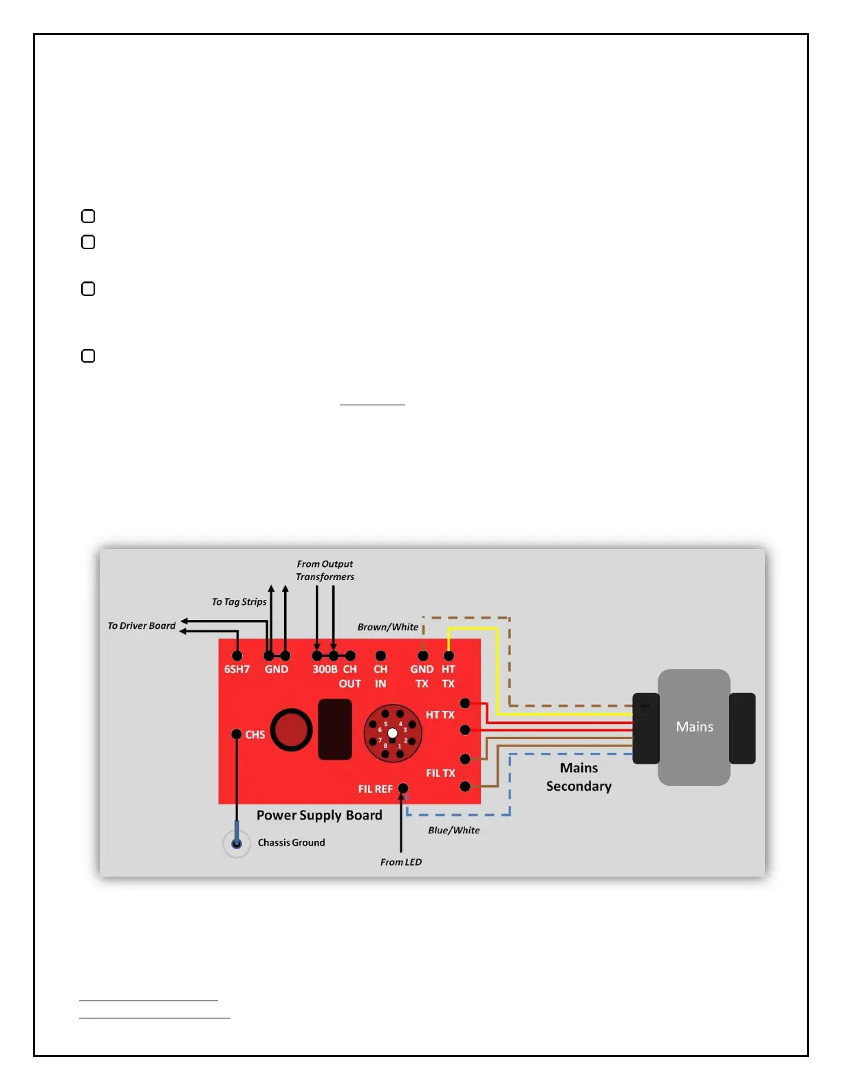
The Blue/White Secondary wire and the Black LED (NEGATIVE) lead will be connected to FIL REF. But
there's a problem: the combination of the tinned Blue/White wire and the Black LED wire will not fit
through the FIL REF solder hole on the board. So, here's how we solve this:
Strip 3/4" of the Black LED wire. Twist it tight but don't tin it.
Insert the Blue/White wire into the FIL REF solder tab from the underside so that about 3/8" of it
protrudes through on the top of the board. Solder it on the underside only.
Twist the end of the Black LED wire around the protruding end of the Blue/White wire
near the
board
. Use your needle-nosed pliers, if it helps. Let's not have any stray wires; ensure a clean
'finish' to the wrap.
Solder this combination Blue/White–Black LED wire on the top of the board.
Trim off the excess Blue/White wire
WITHOUT cutting into the part that has the Black LED wire
wrapped around it
.
7.6 The Remaining Connections
Let's have another look at the wiring diagram.


 To Next Page