26
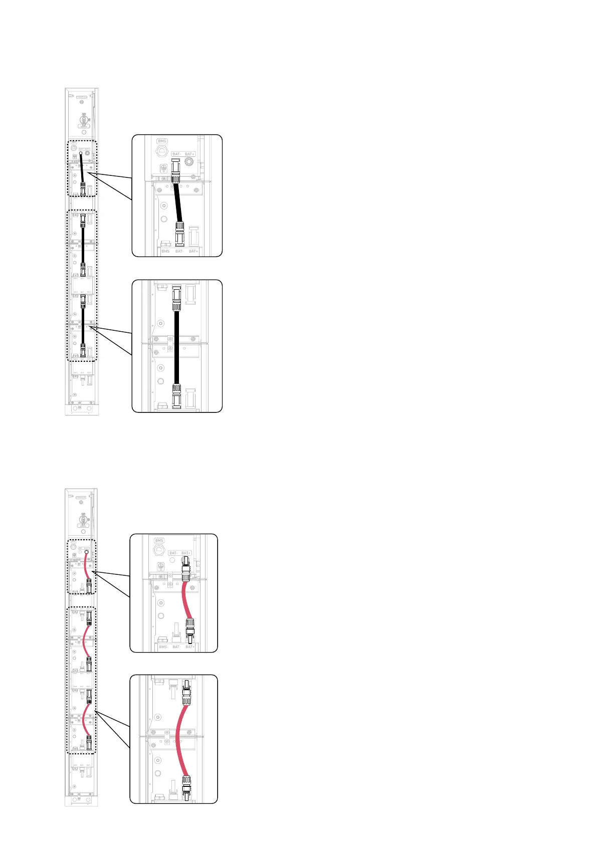
5. Connect the negative DC power cables between the modules.
Insert the negative DC power cables (black, included) into the modules' negative power ports (BAT-).
Figure: Connect negative DC power cables between modules.
BAT
SWITCH
BAT
SWITCH
BMS
BAT- BAT +
POWER ON
BMS B AT- BAT+
BMS B AT- BAT+
BMS B AT- BAT+
BMS B AT- BAT+
BMS B AT- BAT+
BMS B AT- BAT+
6. Connect the positive DC power cables between the modules.
Insert the positive DC power cables (red, included) into the modules' positive power ports (BAT+).
Figure: Connect positive DC power cables between modules.
BAT
SWITCH
BAT
SWITCH
BMS
BAT- BAT +
POWER ON
BMS BAT- BAT+
BMS BAT- BAT+
BMS BAT- BAT+
BMS BAT- BAT+
BMS BAT- BAT+
BMS BAT- BAT+