27
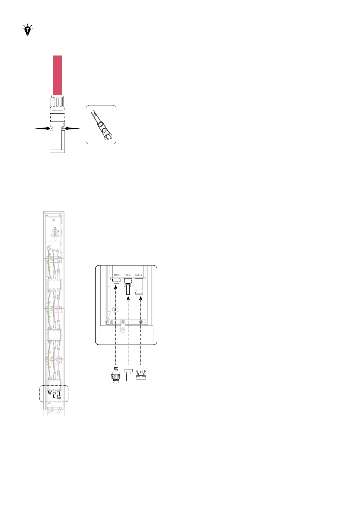
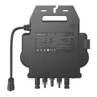
Use a disassembly tool (not included) to remove the connected DC power cables.
Figure: Disconnect the DC power cables.
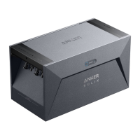
7. Seal unused ports.
On the bottom battery module, insert an RJ45 connector (with 2×120Ω terminating resistor, included) into the BMS port, a
female dustproof cap (included) into the negative DC power port (BAT-), and a male dustproof cap (included) into the positive
DC power port (BAT+).
Figure: Seal unused ports.
BAT
SWITCH
BAT
SWITCH
BMS
BAT- B AT+
POWER ON
BMS BAT- BAT +
BMS BAT- BAT +
BMS BAT- BAT +
BMS BAT- BAT +
BMS BAT- BAT +
BMS BAT- BAT +