29
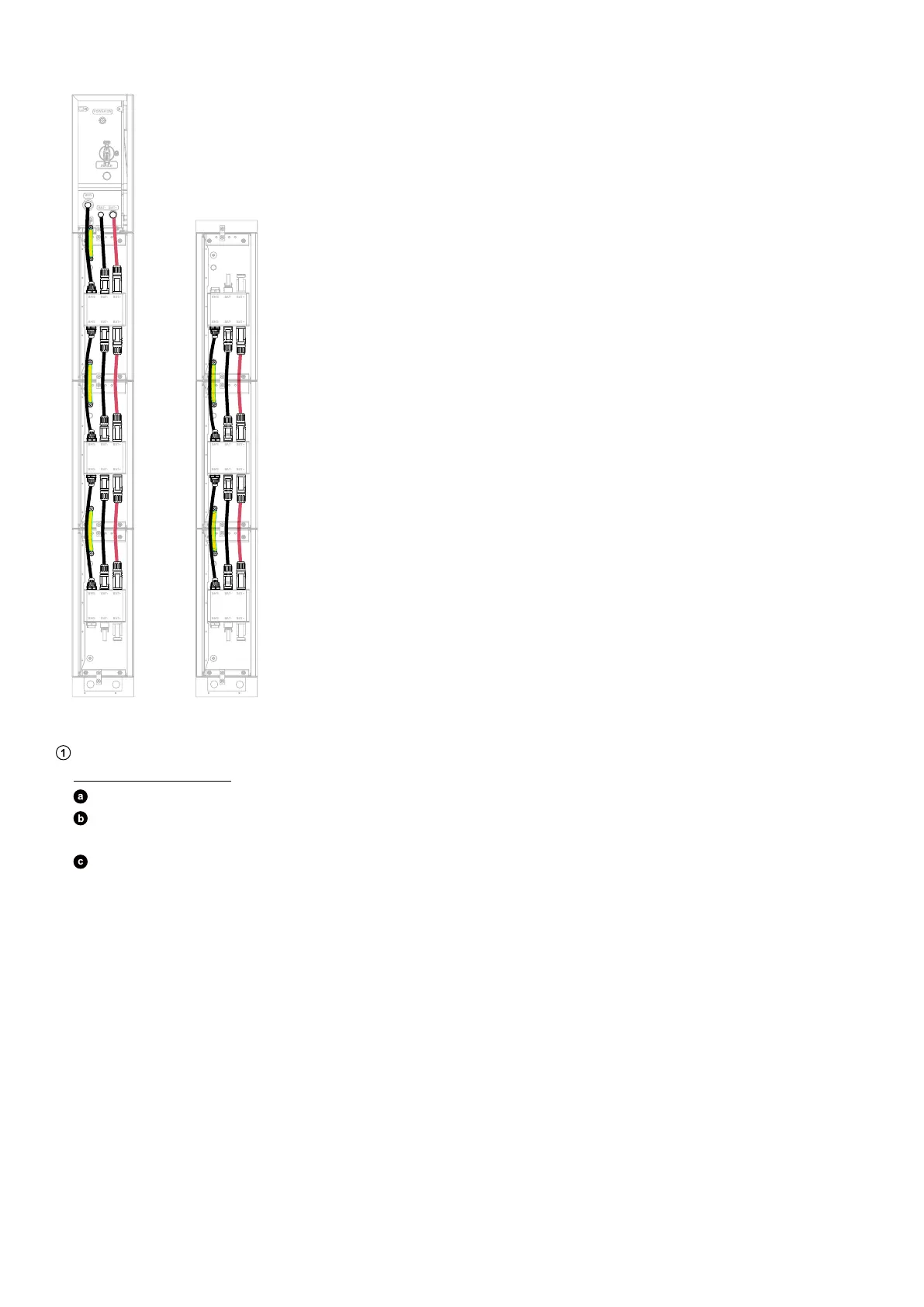
Figure: Connect cables between adjacent modules.
BAT
SWITCH
BAT
SWITCH
BMS
BAT- BAT +
POWER ON
BMS BAT- B AT+
BMS BAT- B AT+
BMS BAT- B AT+
BMS BAT- B AT+
BMS BAT- B AT+
BMS BAT- B AT+
BMS BAT- B AT+
BMS BAT- B AT+
BMS BAT- B AT+
BMS BAT- B AT+
BMS BAT- B AT+
BMS BAT- B AT+
3. Connect cables between the bottom modules.
Thread cables through conduits.
Floor-Mounted Modules
Remove the cable knockouts from the floor mounting base in the first column.
Insert two cable conduits (not included) into the openings. Use rigid metal conduits with an inner diameter of 3/4 in (20
mm) and an outer diameter of 1 in (25 mm), made of 304 stainless steel.
Thread a GND cable (6 mm², yellow/green, not included) and a signal cable (Cat 5 or higher, 5-6 mm in diameter, not
included, shielding recommended) through the cable conduit near the wall.
Thread the positive DC power cable (8 mm², red, not included) and negative DC power cable (8 mm², black, not included)
through the outward cable conduit.