37
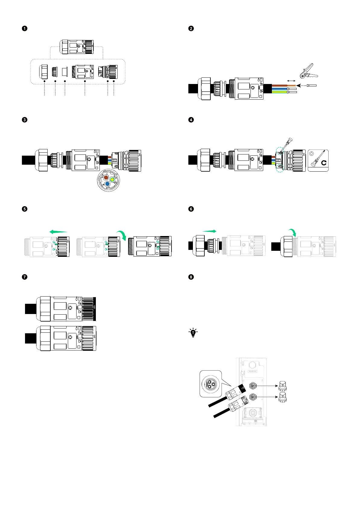
Disassemble an AC connector (included).
Nut Claw Seal body Body Housing Locker
Route the 3-conductor cable (6 mm², not included)
through the nut, claw, seal body, and body. Strip the
insulation layers from the conductors, and insert and
crimp the tube terminals.
10 mm
6 mm²
Connect the L (brown), N (blue), and GND (yellow/green)
conductors to the sockets labelled L, N, and PE (GND)
respectively.
Tighten the three screws on the housing with a No.1
Phillips screwdriver.
#1
0.8 N·m
Align the locker and the body as illustrated, and rotate the
locker until you hear a click.
Tighten the nut to secure the cable.
Repeat steps one to six to assemble the other AC
connector (included).
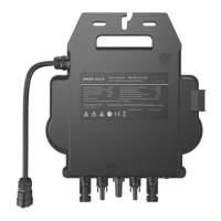
Remove the dustproof covers from the AC ports. Then,
attach the AC grid connector (with a black locker) to the AC
grid port, and connect the AC backup connector (with an
o-white locker) to the AC backup port.
Rotate the locker in the locking direction to tighten the
connectors.
·
You will hear a "click" when the connectors are in place.
·
Slightly pull back the connectors to check whether they are
securely installed.
AC GRID
AC BACKUP
COM