39
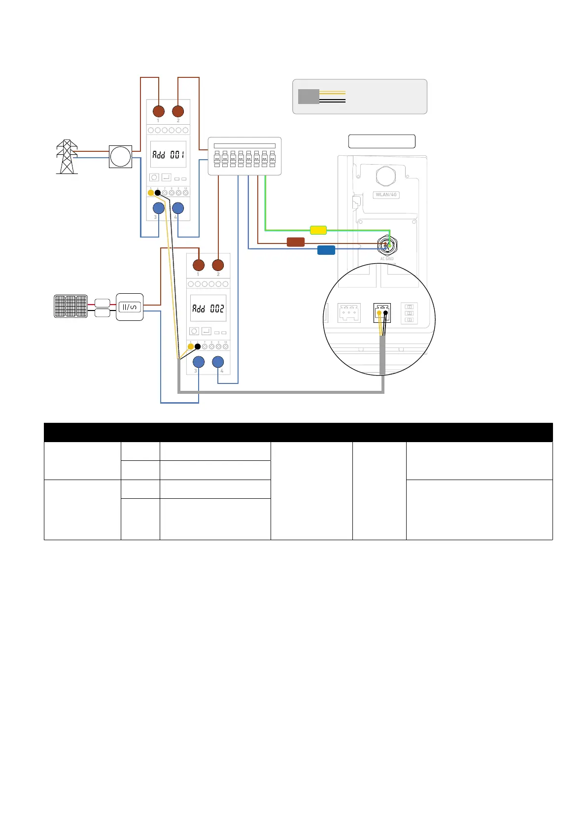
Single-Phase Connection
Figure: Single-phase wiring diagram.
WLAN/4G
AC GRID
AC BACKUP
COM
AC GRID
Grid
Main Meter
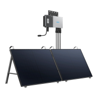
Solar Panels Solar Inverter
Home Main Panel
Power Module
1 2
3 4
3 4
1 2
5 6
5 6
L
PV+
PV-
N
PE
AC GRID
AC BACKUP
COM
AC GRID
485- (485B)485+ (485A)
RS485+ (RS485A)
RS485- (RS485B)
Component Terminal
Definition Wire Size Strip Length Tube Terminal
Power module
485+ RS485 dierential signal+
Outer diameter of
5.5±0.5 mm, conductor
cross-sectional area
of 0.2-0.35 mm², not
included
10 mm
For one conductor (0.2-0.35 mm²), red,
included
485- RS485 dierential signal–
Power sensor
(SDM230-Modbus V1)
5 RS485 dierential signal+
For one conductor (0.2-0.35 mm²), red,
included
For two conductors (0.2-0.5 mm²), yellow,
included
6 RS485 dierential signal–