42
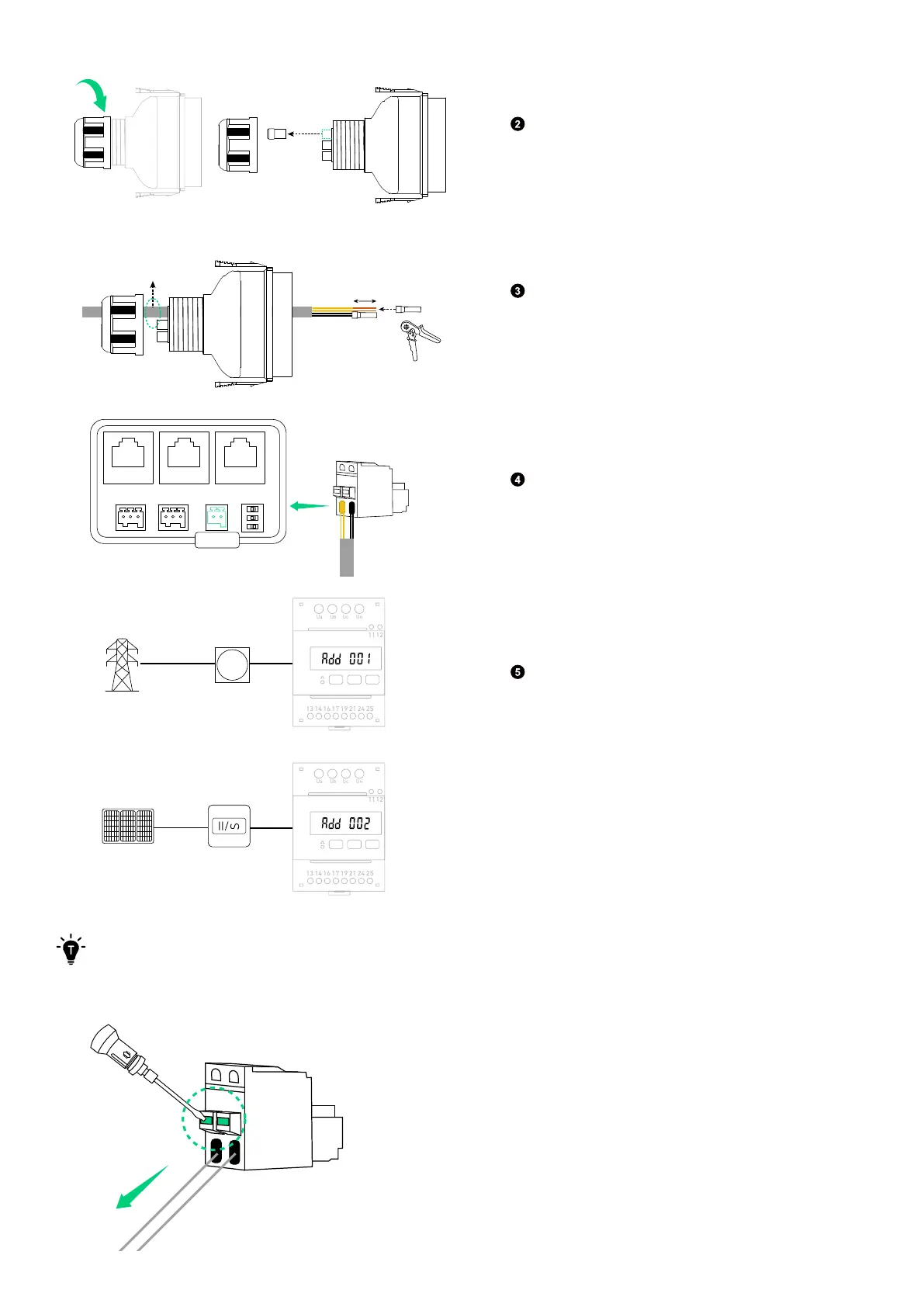
Rotate to remove the locking cap from the wiring
compartment cover. Then take out a waterproof
plug.
(Φ 5.5±0.5 mm)
Ethernet Cable
10 mm
Crimp one tube terminal (for 0.2-0.35 mm²
conductor, included) onto the 485+ (485A)
conductors, and the other tube terminal onto the
485- (485B) conductors.
Meter
485+ (485A) 485- (485B)
Insert the tube terminals into the 2-pin terminal
block connector (included), and plug it into the
terminal block socket labelled Meter.
Grid
Main Meter
Solar Panels Solar Inverter
Ua Ub Uc Un
13 14 16 17 19 21 24 25
1112
Ua Ub Uc Un
13 14 16 17 19 21 24 25
1112
24 25
1112
Connect the power module to the terminals 24
and 25 of the grid-side power sensor, and to the
terminals 11 and 12 of the solar-side power sensor.
This will ensure that the communication address
is correctly established. If not, please reset the
address by checking the power sensor manual.
Power sensor on the grid side: Add 001
Power sensor on the solar panel side: Add 002
To disconnect a conductor, press the tab and pull the conductor out.
Figure: Disconnect the conductor.