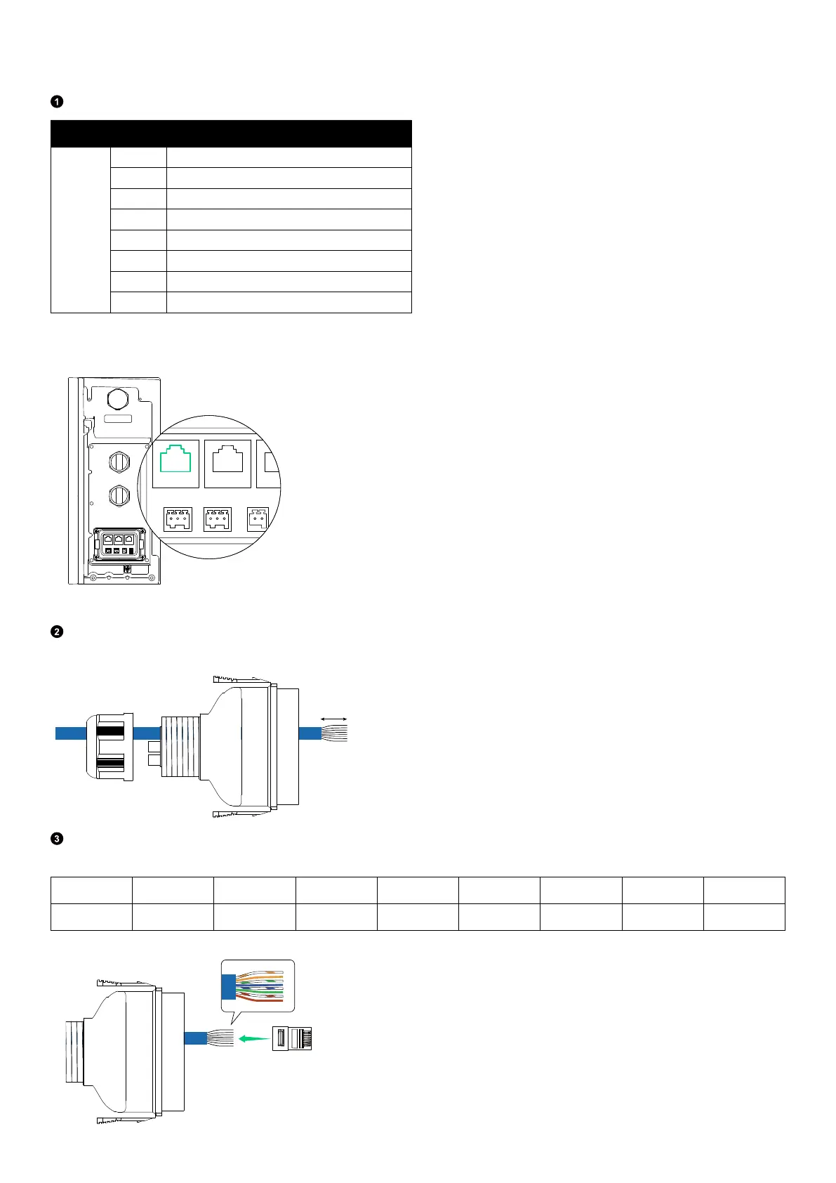
43
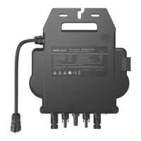
Connect to the Demand Response Enabling Device (DRED)
Connect the power module to the Demand Response Enabling Device (DRED).
Identify the terminals to connect based on the table below.
Terminal Pin
Definition
DRM
1 DRM1/5
2 DRM2/6
3 DRM3/7
4 DRM4/8
5 DRM REF
6 DRM COM
7 /
8 /
Figure: DRM port of the power module.
WLAN/4G
AC GRID
AC BACKUP
COM
Route a signal cable (Cat 5 or higher, 5-6 mm in diameter, not included; shielding recommended) through the locking cap
and wiring compartment cover. Then, strip the insulation layer.
25 mm
Insert the wires into the RJ45 connector (included) in the EIA/TIA 568B order. From left to right (when the clip is facing
away from you):
Pin 1
2 3 4 5 6 7 8
Wire Color Orange-white Orange Green-white Blue Blue-white Green Brown-white Brown
12345678