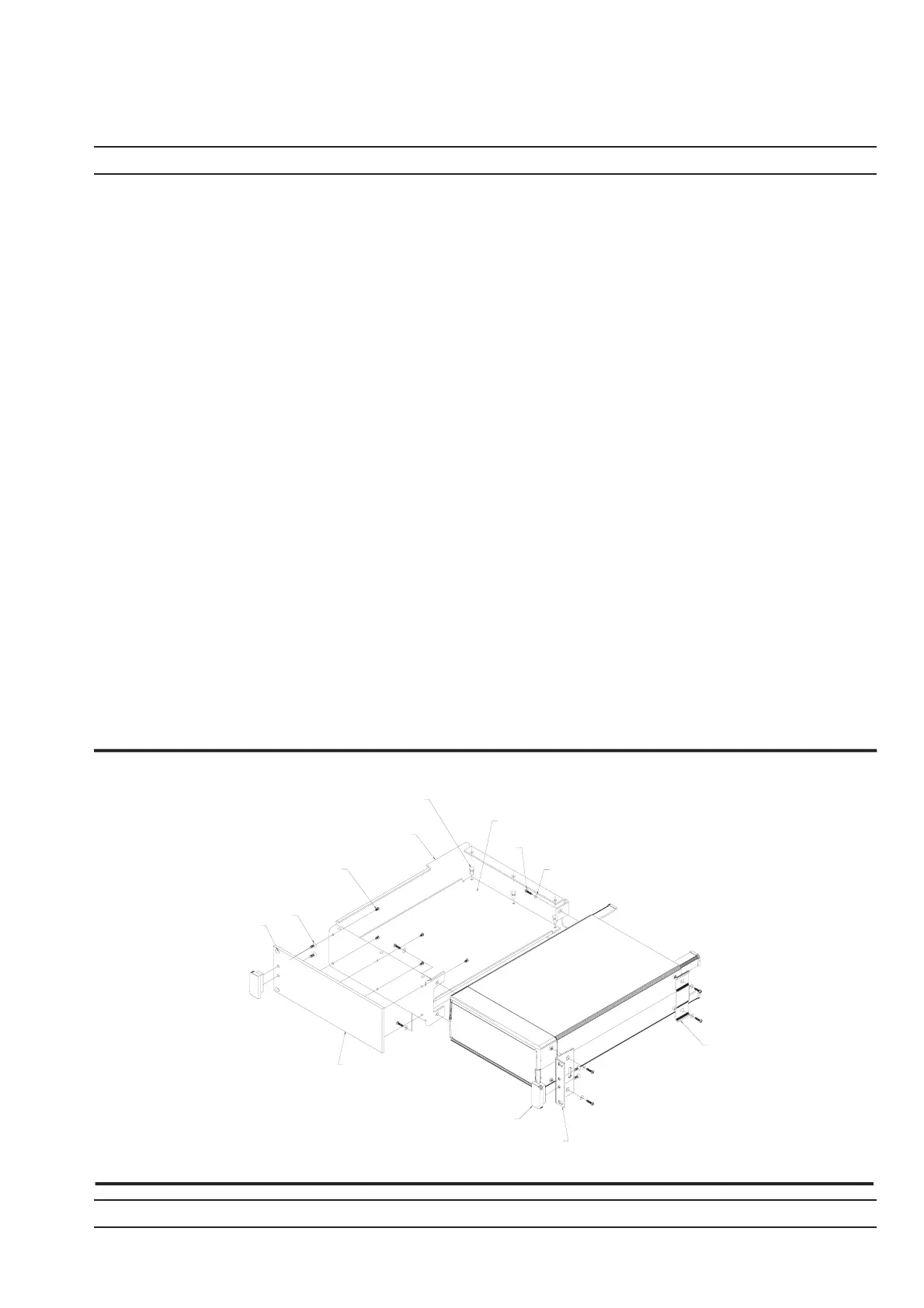
3. Lay the large support bracket D41473 next to the Power Meter as per the as-
sembly drawing. Note if the PM needs to be mounted on the left hand side of
the rack, simply lay the bracket on the PM,s right side. i.e. a mirror image of
the assembly drawing.
4. Locate the support bracket on the four PM case pillars. Secure with 4 screws
905-68 and 4 washers 900-345. (See max. torque settings page 2-4).
5. Locate the front rack mounting bracket C37276 at the front of the PM on the
other side to the large support bracket with two screws 905-68 and two
washers 900345. (See max. torque settings page 2-4).
6. Locate the rear bracket C41449 at the back of the PM on the other side to the
large support bracket with two screws 905-68 and two washers 900-345. See
maximum torque settings above. Locate the rear bracket C41449 at the back
of the PM on the other side to the large support bracket with two screws
905-68 and two washers 900-345. (See max. torque settings page 2-4).
7. Fit the front plate 49362 with 6 screws 905-72. (See max. torque settings
page 2-4).
8. Position the base panel 49361 as shown in the drawing, and secure with 6
snap rivets 788-575.
9. Fit the four speed nut 790-319 to the rack in the correct place to allow mount-
ing of the PM in the rack.
10. Slide the PM into the rack and secure with 4 decorative screws 900-821.
ML2400A OM 2-5
INSTALLATION RACK MOUNTING
49362
FRONT PLATE
900-795
X4
905-72
X6
SCREW
041473
SUPPORT
BRACKET
49361
BASE PANEL
788-575
X6
SNAP RIVET
PRESS DOWN CENTER
PIN USING A FLAT EDGE
905-68
X8
900-345
X8
C41449
RACKMOUNT
BRACKET
REAR SUPPORT
C37276
RACKMOUNT
SIDE BRACKET
783-1055
HANDLE
X2
NOTE:
FIT COMPLETED
ASSEMBLY TO RACK USING
DECORATIVE SCREW 900-821
X4 AND SPEED NUT 790-319
X4 IN 4 CORNER
POSITIONS AS SHOWN