ML2400A OM 3-3/3-4
OPERATION REAR PANEL CONNECTORS
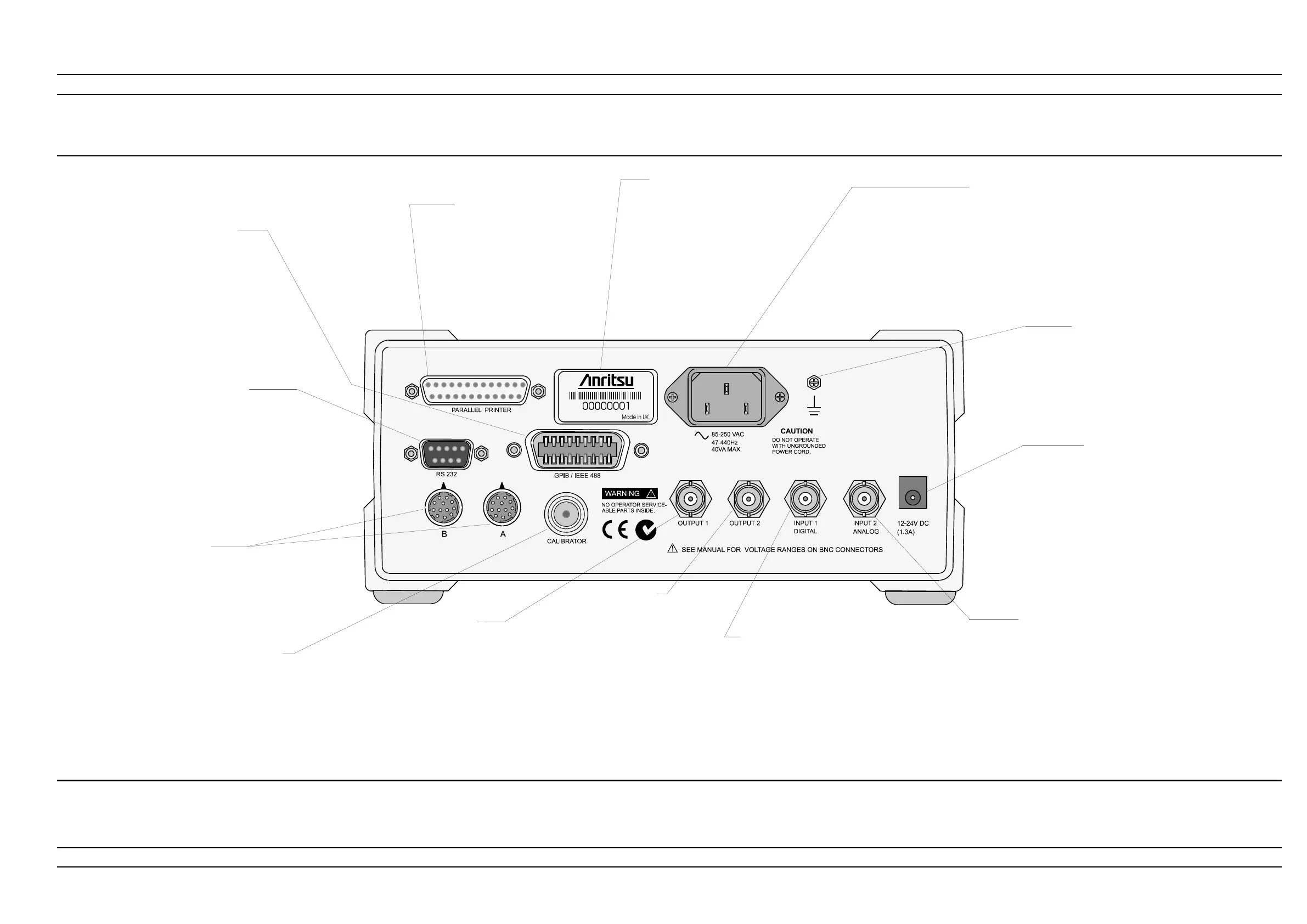
Figure 3-2. ML2400A Se ries Rear Panel
GPIB/ IEEE488 Con nec tor
Stan dard Gen eral Pur pose In ter -
face Bus con nec tor used to con -
nect through GPIB to other test
equip ment and a host com puter.
The ML2400A Se ries is com pati ble
with IEEE- 488.1 re quire ments. Re -
fer to Chap ter 6, GPIB Pro gram -
ming for in for ma tion on us ing
GPIB.
Par al lel Printer Port
Pro vides an in ter face to a stan -
dard par al lel printer. Com pat i ble
print ers in clude the Canon BJC80,
HP 340 Deskjet, and most other
300 and 500 Se ries HP Deskjet
print ers.
ID Num ber La bel
The ML2400A Se ries ID
number is af fixed to the rear
panel here. Please use the
com plete ID number when
or der ing parts or cor re -
spond ing with the Anritsu
Cus tomer Serv ice de part -
ment.
AC Main Power In put
85- 264 VAC, 47- 440 Hz, 40 VA maxi mum. The Power Me ter auto mati cally
con fig ures it self for the volt age ap plied. Con nect ing AC power here will
turn the in stru ment on. Sub se quently, the in stru ment can be switched be -
tween the ON state and the STANDBY state us ing the front panel ON/OFF
but ton. The op tional bat tery can be fast charged when AC in put volt age is
ap plied through this con nec tor and all other Power Me ter func tions are off.
RS232 Se rial Con nec tor
Se rial con trol and data out put com mands are
en tered us ing the same for mat as the GPIB in -
ter face. Re fer to Sec tion 5-9 for more in for ma tion
on us ing Se rial Re mote Op er a tion. Al lows com -
mu ni ca tion with an Anritsu 68/69000-series syn -
the sizer in Source Sweep mode. Also al lows ser -
vice ac cess for soft ware up grades, etc. The
hard ware hand shake lines RTS and CTS are
used to con trol the flow of data.
Sen sor Con nec tors
Al ter nate Sen sor in put con nec -
tors for Chan nels A and B. If the
rear panel op tional con nec tors
are in stalled, the front panel
con nec tors are not in stalled.
Cali bra tor Con nec tor
Al ter nate Cali bra tor out put con -
nec tor. If this rear panel con nec tor
op tion is in stalled, the front panel
con nec tor is not in stalled. Re fer to
Chap ter 5, Pro ce dures, for in for -
ma tion on us ing the Ref er ence
Cali bra tor out put.
Chas sis Ground
Used as a con ven ient earth ground
ref er ence when DC line power is
ap plied and an op tional safety
ground when op er at ing from bat tery
power.
DC Power Sup ply In put
Used for 12- 24 VDC in put in the ab sence of AC
line power. The op tional bat tery can be fast
charged when the DC in put volt age is greater
than or equal to 21V and all other func tions are
off. Fast charge must be se lected from the
Sys -
tem menu. The ex ter nal DC Power Sup ply in put
line is pro tected by an in ter nal fuse
Out put 1
Multi-purpose BNC con nec tor is user
configurable for Mod u la tion Out put
(TTL ), An a log Out put 1 (volts/units),
or Limits Pass/fail ( TTL ). Sup ports
pass/fail test ing for chan nels 1 and 2.
Also configurable to out put a
real-time mea sure ment sig nal from
sen sor in put A, suitable for lev el ing
pur poses.
Out put 2
Multi pur pose BNC con nec -
tor is user con fig ur able for
Ana log Out put 2 (volts/units),
Blank ing Zero ( TTL ), or Lim -
its Pass/Fail ( TTL ). Sup ports
pass/fail test ing for chan nels
1 and 2. Also con fig ur able to
out put a real- time meas ure -
ment sig nal from sen sor in -
put B, suitable for lev el ing
pur poses.
In put 1, Digi tal
Multi pur pose BNC con -
nec tor is user con fig ur -
able for Blank ing In put
(used to ARM meas ure -
ments in trig ger ing
modes) or TTL Trig ger
In put.
In put 2, Ana log
Multi- purpose BNC con nec tor used for Volts per GHz con nec tion. Sup ports 0 to
+20V nomi nal in put volt age with soft ware se lecta ble scal ing. V/ GHz is used for
auto matic CAL FAC TOR cor rec tion by ap ply ing an ex ter nal volt age, scaled to fre -
quency. The cor rect cali bra tion fac tor for this fre quency is auto mati cally in ter po -
lated and ap plied when in V/ GHz cali bra tion fac tor mode. Dif fer ent scal ing may be
ap plied to sen sor A or B al low ing for meas ure ment of fre quency trans la tion de vices.
Avail able si mul ta ne ously with chan nel A and/or B data, the data rate is as set on the
chan nel. The de fault data rate is 20 ms in DE FAULT meas ure ment mode (with the
de fault set tling time of 0.1%), and pro gram ma ble in PRO FILE op era tion mode and
CUS TOM meas ure ment mode.