1. Con nect to the rear panel dig i tal in put.
2. Se lect
Trig ger|Setup|ARMING|Blanking ON .
3. Set the po lar ity of the blank ing (Sys tem menu)
Ex am ple power me ter read ing: –9.16 dBm.
TYPE
[TRGTYP
GTTYP]
The Type se lec tion (RISE or FALL) sets the trig ger for a ris ing or
fall ing edge. When the trig ger source is set to INTA or INTB (In -
ter nal A or B) the power me ter trig gers on a power level which is
ris ing or fall ing.
LEVEL
[TRGLVL
GTLVL]
The Level se lec tion sets the in ter nal trig ger level. When the trig -
ger source is set to ei ther INTA or INTB (in ter nal sen sor A or B)
the chan nel trig gers on a power level (in dBm) given by the sen -
sor. This value must not take any cal fac tors or off sets that the
me ter ap plies into ac count.
Trig 1 If Trig ger Chan nel 1 SOURCE is set to Man ual, this softkey ini ti -
ates a mea sure ment for chan nel 1.
Trig 2 If Trig ger Chan nel 2 SOURCE is set to Man ual, this softkey ini ti -
ates a mea sure ment for chan nel 2.
Trig 1&2 If Trig ger Chan nels 1 and 2 SOURCE are set to Man ual, this
softkey trig gers both chan nels simultaneously.
ML2400A OM 4-19
OPERATION TRIGGER MENU
NOTE
Ef fec tive range is to ap -
prox i mately –30 dBm
and is only ac tive in DC
ranges 1 and 2.
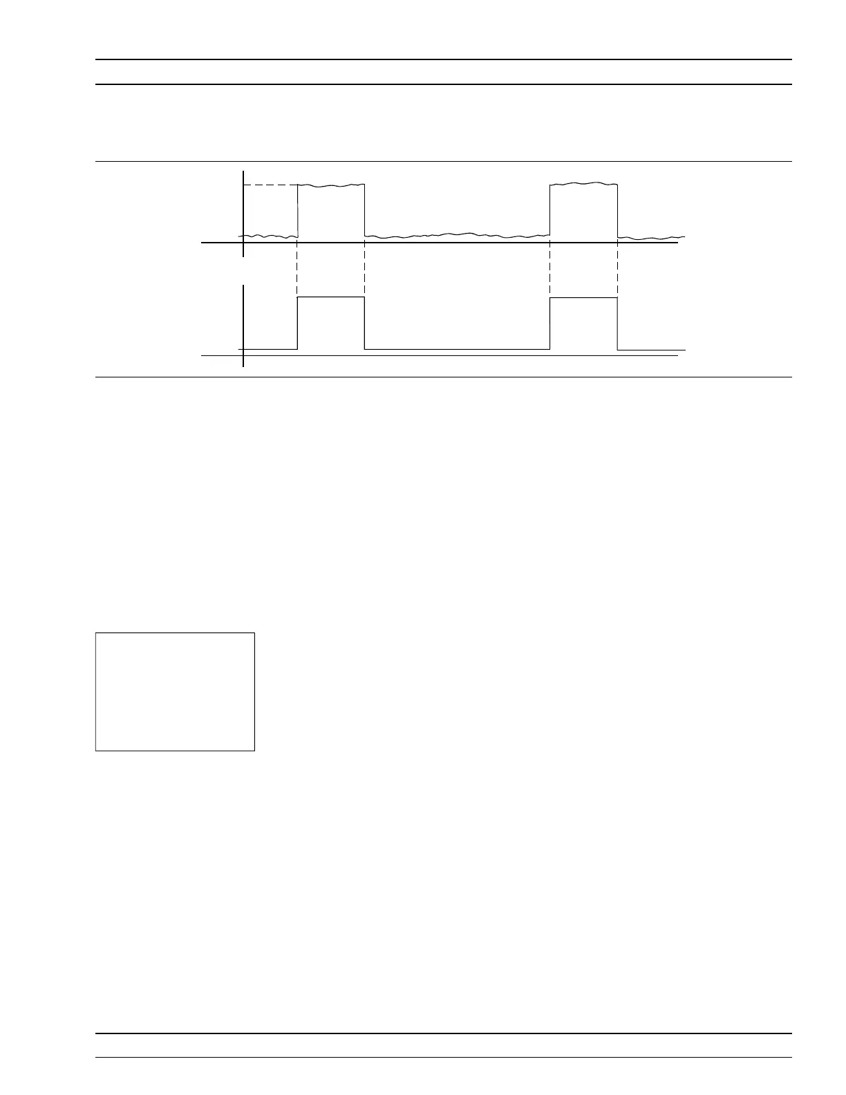
-9
dBm
-50
TTL
GSM BURSTFROM GENERATOR
BURST TRIGGER SYNCFROM GENERATOR
Fig ure 4-3. Typical Arming Diagram