NOTE: The antenna must be connected at the end of the transmission feed line
when conducting a System Return Loss measurement.
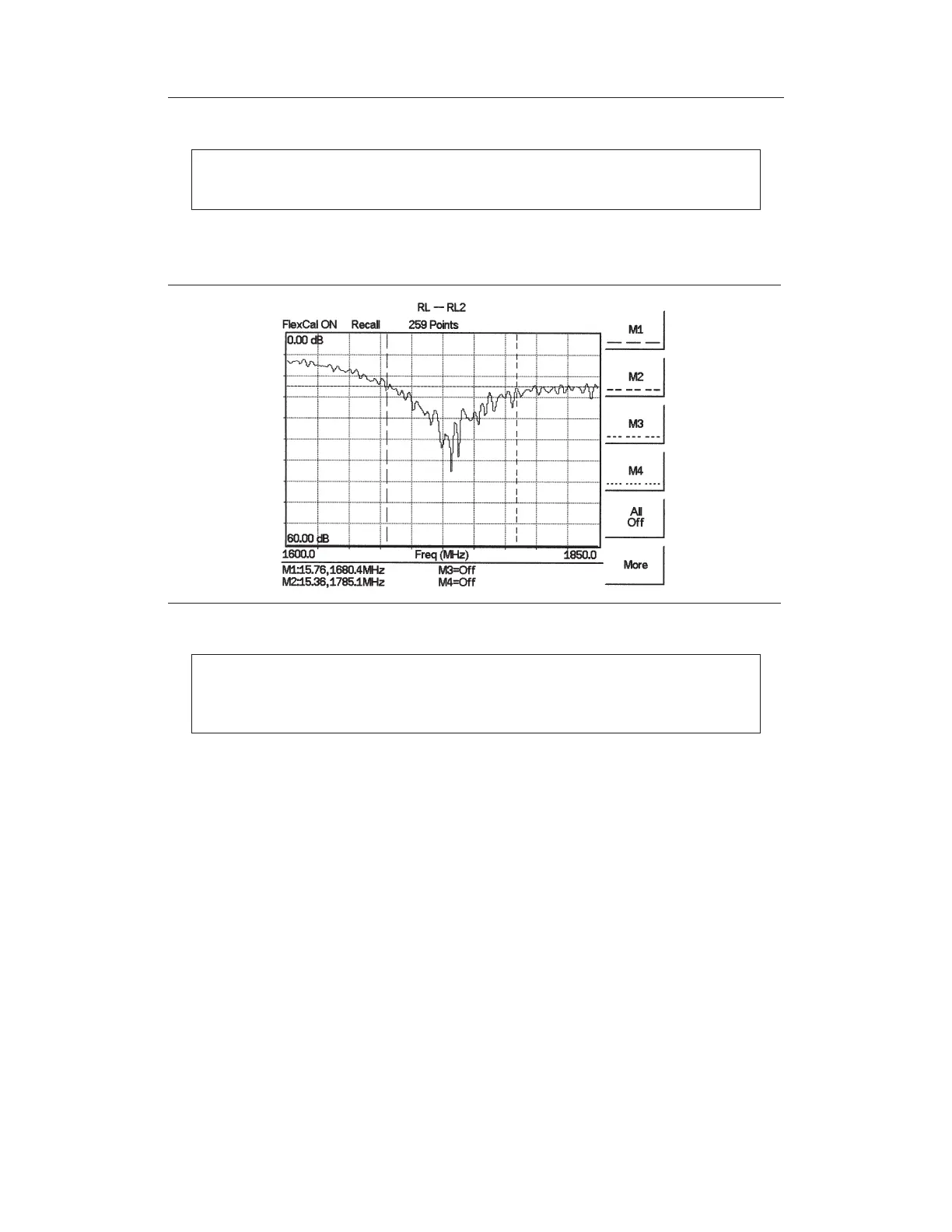
Figure 4-2 is an example of a typical system return loss measurement trace using a FlexCal
calibration:
NOTE: The system sweep trace should appear at an approximate return loss of
15 dB (±3 dB) in the status window. Typically, greater than a 15 dB return loss
is measured in the passband of the antenna system.
Cable Loss Measurement
The transmission feed line insertion loss test verifies the signal attenuation level of the ca
-
ble system in reference to the specification. This test can be conducted with the Site Master
in Freq–Cable Loss mode.
Required Equipment
q
Site Master Model S331D/S332D
q
Precision Open/Short, Anritsu 22N50 or
Precision Open/Short/Load, Anritsu OSLN50-1 or
Anritsu InstaCal Module, ICN50
q
Precision Load, Anritsu SM/PL-1
q
Test Port Extension Cable, Anritsu 15NNF50-1.5C
q
Optional 510-90 Adapter, DC to 7.5 GHz, 50 ohm, 7/16(F)-N(M)
Device Under Test
q
Transmission Feed Line with Short
4-4
Chapter 4 Cable & Antenna Measurements
Figure 4-2. Typical System Return Loss Trace