Figure 3-6
Parameter
Grounding Alarm
Alarm Input 1, 2, …, 8. It becomes valid in low voltage.
1-NO C,
2-NO C,
Three NO activation outputs.
1,2,3,4: NO and C(Normally Open and Com)
5: NO,C and NC(Normally Open, Com, Normally Closed)
6: Ctrl 12V(This is used for reset the senor)
485 A/B 485 communication port. They are used to control devices such as
PTZ. Please parallel connect 120Ω between A/B cables if there are
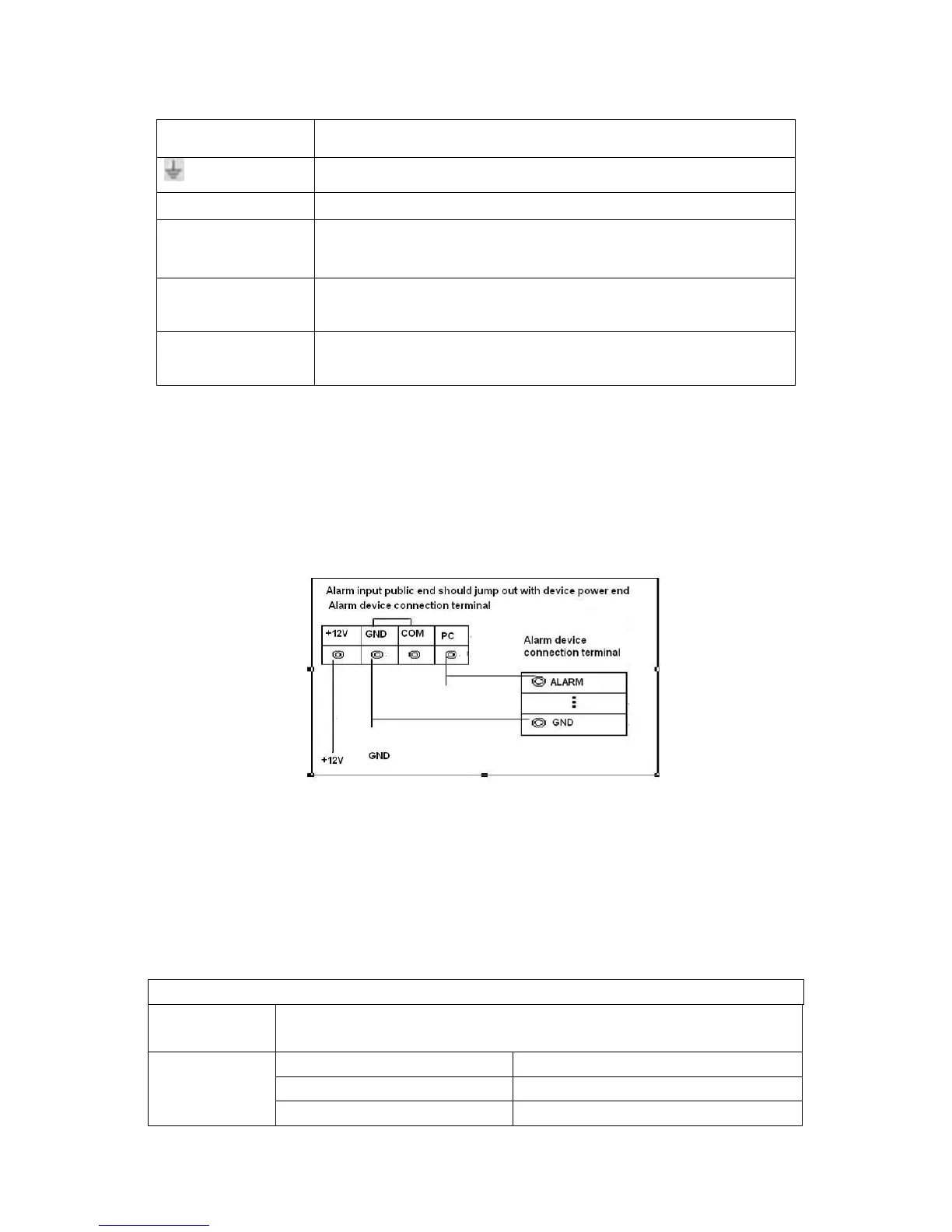
3.7.2 Alarm Input Port
Please refer to the following sheet for more information.
4/8/16-ch grounding alarm inputs. (Normal open or Normal close type)
Please parallel connect COM end and GND end of the alarm detector (Provide external
power to the alarm detector).
Please parallel connect the Ground of the DVR and the ground of the alarm detector.
Please connect the NC port of the alarm sensor to the DVR alarm input(ALARM)
Use the same ground with that of DVR if you use external power to the alarm device.
Figure 3-7
3.7.3 Alarm Output Port
3 ways relay alarm output (NO contact). Provide external power to external alarm device.
To avoid overloading, please read the following relay parameters sheet carefully.
RS485 A/B cable is for the A/B cable of the PTZ decoder.
Relay Specification
Model:
JRC-27F
Material of the
touch
(Resistance
Load)
Rated switch capacity 30VDC 2A, 125VAC 1A
Maximum switch power 125VA 160W
Maximum switch voltage 250VAC, 220VDC