CHAPTER 5
APPLICATIONS
Entire Contents Copyright 2004 by Adaptive Power Systems, Inc. (APSI) • All Rights Reserved • No reproduction without written authorization from APSI.
APS-3000P Series 5 - 6 OM-001-03000-00P-03.9
Standard Remote Control Interface (RS-232)
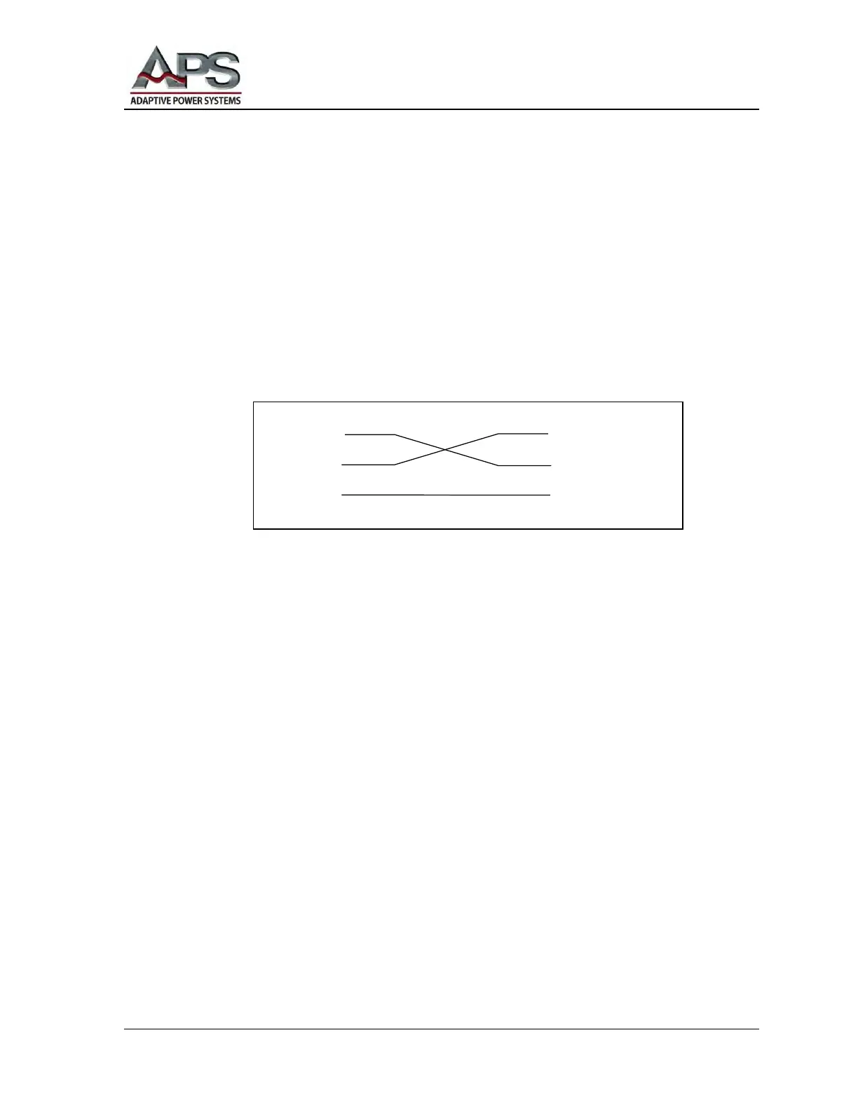
The following illustration shows how to connect your RS-232 Data Communications
port to the APS RS-232 External Communications port. Both the APS external port
and the connected computer are wired as Data Communications Equipment (DCE)
ports. Consequently, a cross-over cable is required. If you don't use a cross-over cable,
you will be connecting transmit-to-transmit and receive-to-receive. That will not work.
The RS-232 serial port uses a simple 3-wire interface. The subminiature d-shaped shell
(D-sub) DE-9 pin connections for the APS-3000P and the RS-232 controller are shown
in the following figure:
Instructions and Strings
As indicated in the RS-232 Setup Checklist, the RS-232 serial port of your computer
should be configured for 9600 bps, 8 data bits, 1 stop bit, and no parity. There is no
complex software protocol. There is no hardware handshaking.
Individual instructions or character strings are sent from your computer to the APS unit
via the RS-232 connection. Transmitted characters are either accepted or rejected by
the APS RS-232 port controller. Characters that are accepted are echoed-back.
However, if there are errors, the APS RS-232 port controller will response with the
code NAK = (15H) . When the command string transmission is complete, an ending
code LF = (0AH) should be added, for example:
TEST + LF
APS Power Converter PC / Bus Controller