CHAPTER 5
APPLICATIONS
Entire Contents Copyright 2004 by Adaptive Power Systems, Inc. (APSI) • All Rights Reserved • No reproduction without written authorization from APSI.
APS-3000P Series 5 - 11 OM-001-03000-00P-03.9
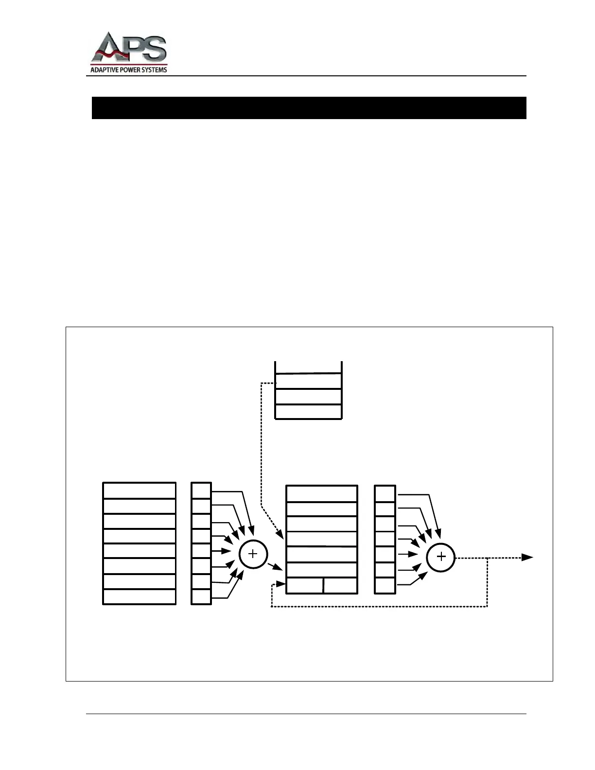
GPIB Standard Status Data Structure
The following figure shows the Standard Status Data Structure and the complete data
structure diagram. This information is used by instrumentation programmers who are
familiar with GPIB or the IEEE488 Standard.
A registers-mode status structure is used. The model defines the Standard Event Status
Register (SESR) and the Standard Event Status Enable Register (SESER). These
registers generate the Event Status Bit (ESB) summary information (status byte register
bit 5).
Note the queue-data structure. The model defines an output queue that becomes a
sequence of output data. This data is used to obtain Message Available (MAV)
information (status byte register bit 4).
1
Operation Complete
Not Used
Query Error
Not Used
Execution Error
Command Error
Not Used
Power On
1
2
4
8
16
32
64
128
1
2
4
8
16
32
64
0
1
2
3
4
5
6
7
0
1
2
3
4
5
6
Pass
Fail
About
Processing
MAV
ESB
MSB ROS
Status Register
Non-Empty Queue
*ESR
*ESE?
*ESE<NRf> *STB? SPOLL
*SRE?
*SRE<NRf>
OR
OR
SRQ generation
Service Request Enable RegisterStatus Enable
Resister
Status Byte Register