CHAPTER 6
INSTRUMENTATION CALIBRATION
Entire Contents Copyright 2004 by Adaptive Power Systems, Inc. (APSI) • All Rights Reserved • No reproduction without written authorization from APSI.
APS-3000P Series 6 - 2 OM-001-03000-00P-03.9
Calibration Setup
APS-3000P calibration is straightforward. However, you must use the appropriate
calibration instrumentation and text fixtures. In addition to test cables and connectors,
you will need:
RMS Voltmeter, 0.2%, at least 300 VAC
RMS Ammeter, 0.2%, (See Calibration Settings Table for your APS model)
Restive Load Bank, Calculated for your APS model (See following Example)
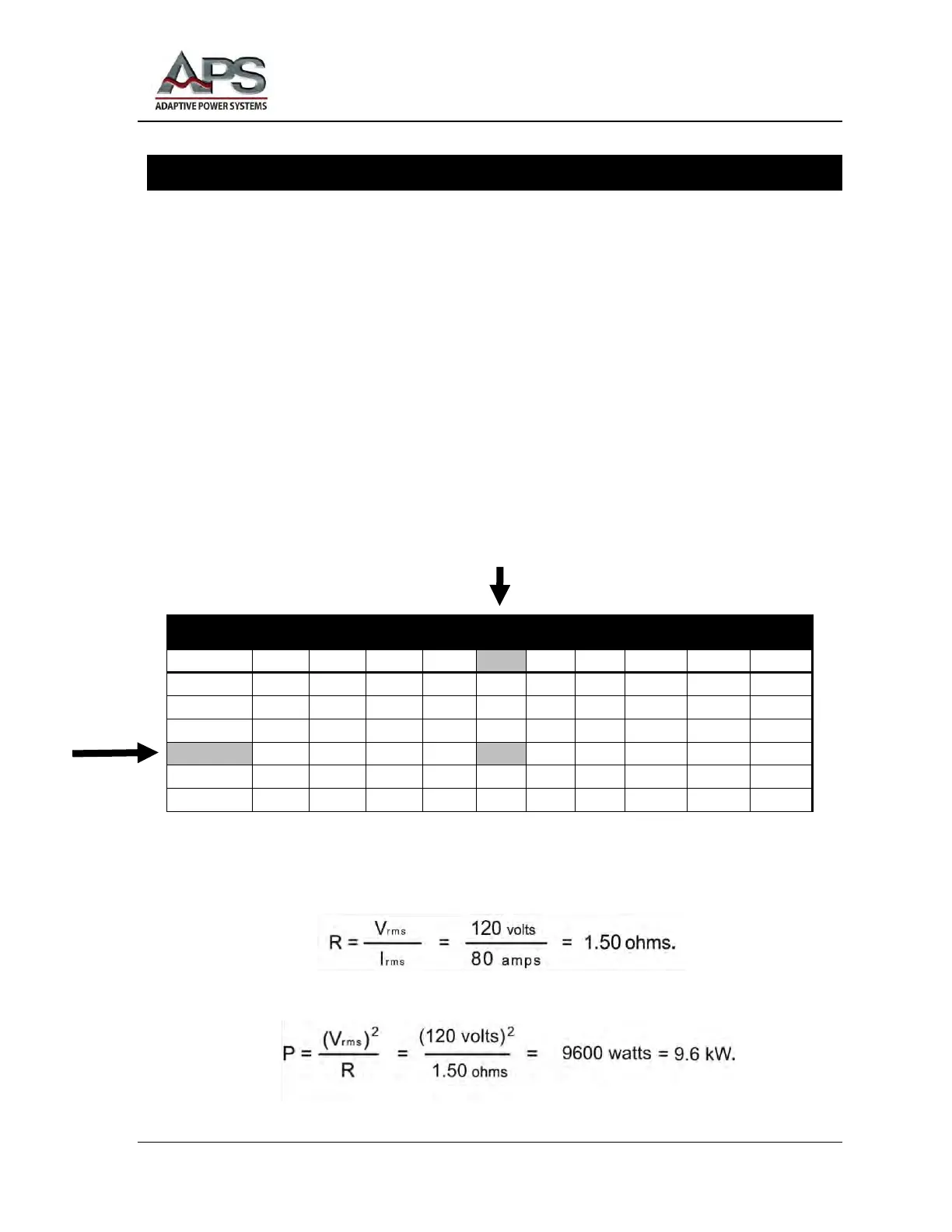
How to Calculate the Size of the Test Load (Example)
For an example, suppose your system is an APS-3030P.
The High Current Calibration Procedure (later in this chapter) specifies an output
voltage of 120 VAC, for all models. From the Table of Calibration Settings, you see
the A HI (A) calibration test current for the (example) APS-3030P is specified at 80 A
per phase.
For 100 VAC and 80 A, each leg of your 3- phase load bank should have a resistance of
The power handling capability of each resistive leg of the test load must be at least