5 Installation and Connection
(continued)
5-8
C232-302-401/402/403/404-603 / C232/EN M/A23
Connecting the time-
overcurrent protection
measuring circuits
C232 could be equipped with up to four current or voltage transformers. The applicable
assignment of the terminal connections is described in the Appendix (E). The C232
model 4 (with time-overcurrent protection) is fitted with four current-measuring inputs as
a standard.
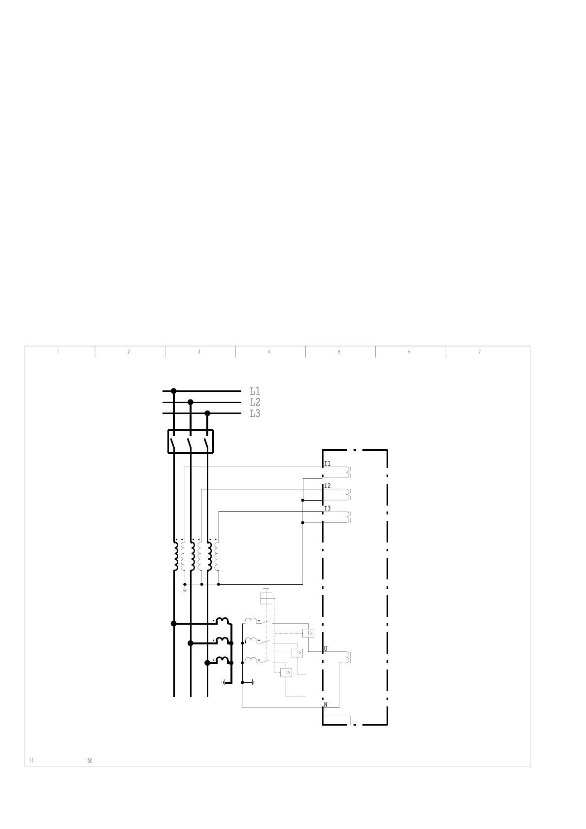
The system current and voltage transformers must be connected in accordance with the
standard schematic diagram shown in Figure 5-6. It is essential that the grounding
configuration shown in the diagram be followed. If a connection is in opposition, this can
be taken into account when making settings (see Chapter 7).
C232
22Z5112A
5-6 Standard schematic diagram for time-overcurrent protection