8 Information and Control Functions
(continued)
8-18
C232-302-401/402/403/404-603 / C232/EN M/A23
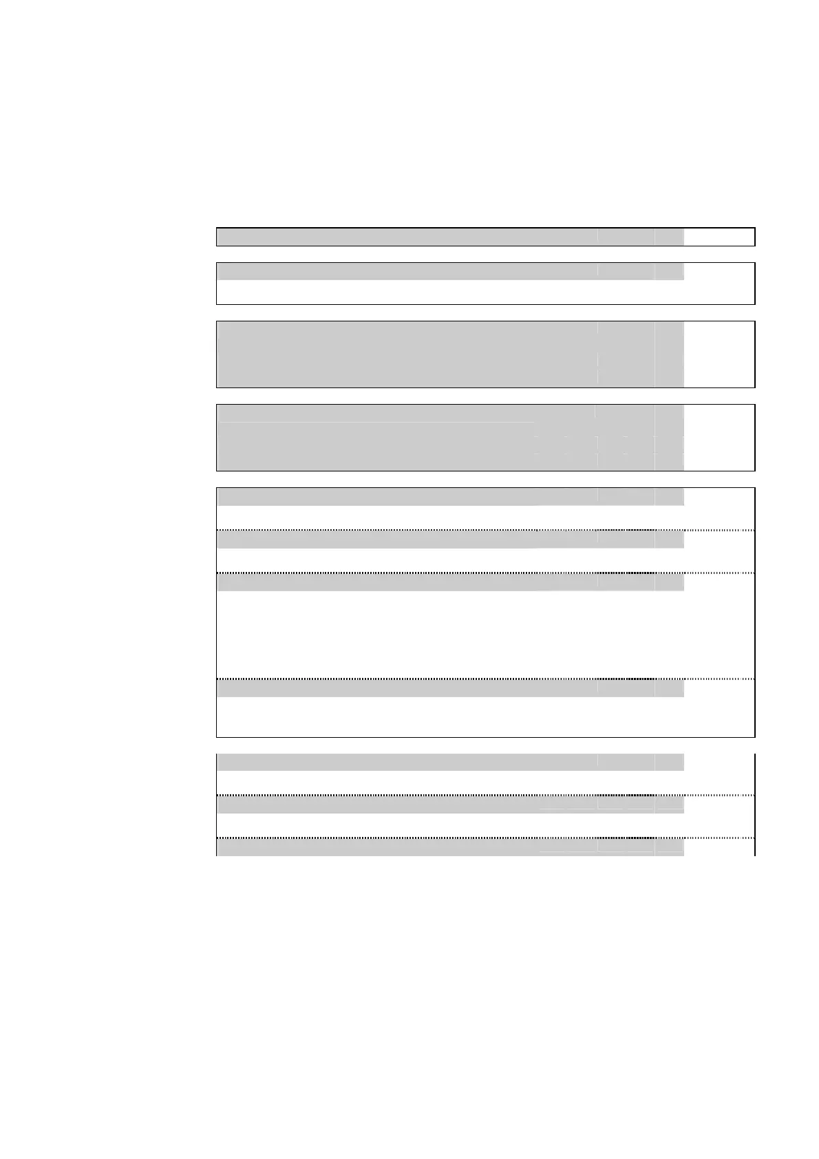
8.1.2 Control and Testing
Device
DVICE: Service info 031 080
031 080
Local control panel
LOC: Param. change enabl.
003 010
Setting the enable for changing values from the local control panel.
“Logical“ communication
interface 1
COMM1: Sel.spontan.sig.test
003 180
Fig. 3-13
COMM1: Test spont.sig.start
003 184
Fig. 3-13
COMM1: Test spont.sig. end
003 186
Fig. 3-13
“Logical“ communication
interface 2
COMM2: Sel.spontan.sig.test
103 180
Fig. 3-15
COMM2: Test spont.sig.start
103 184
Fig. 3-15
COMM2: Test spont.sig. end
103 186
Fig. 3-15
Binary outputs
OUTP: Reset latch. USER
021 009
Fig. 3-22
Reset of latched output relays from the local control panel.
OUTP: Relay assign. f.test
003 042
Fig. 3-23
Selection of the relay to be tested.
OUTP: Relay test
003 043
Fig. 3-23
The relay selected for testing is triggered for the set time (OUTP: Hold-
time for test).
This control action is password-protected (see section entitled ‘Password-
Protected Control Operations’ in Chapter 6).
OUTP: Hold-time for test
003 044
Fig. 3-23
Setting for the time period for which the selected output relay is triggered for
functional testing.
Main function
MAIN: Enable syst. IN USER
003 142
Fig. 3-38
Enabling the residual current stages of the DTOC/IDMT protection.
MAIN: Disable syst.IN USER
003 141
Fig. 3-38
Disabling the residual current stages of the DTOC/IDMT protection.
MAIN: General reset
003 002
Fig. 3-59