6 Local Control Panel
(continued)
C232-302-401/402/403/404-603 / C232/EN M/A23 6-7
The following presentation of the individual control steps shows which displays can be
changed in each case by pressing the keys. A small black square to the right of the
enter key indicates that the “EDIT MODE” LED indicator is lit up. An underscored
external device name in the Bay Panel indicates a selected switchgear unit. The
examples used here are not necessarily valid for the unit type described in this manual;
they merely serve to illustrate the control principles involved.
6.2 Changing between Display Levels
After start-up of the unit, the display is at the Panel level. The Bay Panel is displayed.
Control Step / Description Control
Action
Display
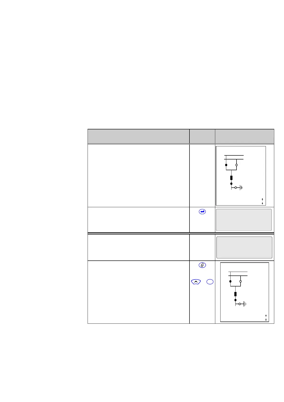
Jumping from the Panel level
to the menu tree level
0 Example of a display after start-up of the
unit.
Note:
When the unit is delivered, it is set for a dummy
bay without switchgear units. Therefore only
the name of the unit appears on the Bay Panel.
The display shown in the example will not
appear until a ‘real’ bay type has been
selected.
X YYY 10:33:22
SS1
SS2
Q1 Q2
Q0
Q8
Locked
Remote
Q9
1088 A
Curr. IP,max prim.
1 Press the enter key to go from the Panel
level to the menu tree level.
X YYY
Parameters
Jumping from the menu tree
level to the Panel level
0 From the menu tree level, the user can go to
the Panel level from any position within the
menu tree.
Par/Func/Glob/MAIN
Device on-line
No (=off)
1 Press the page key.
Alternatively first press the ‘up’ key and hold it
down while pressing the reset key.
Note:
It is important to press the ‘up’ key first and
release it last in order to avoid unintentional
resetting of stored data.
or
+
C
X YYY 10:33:22
SS1
SS2
Q1 Q2
Q0
Q8
Locked
Remote
Q9
1088 A
Curr. IP,max prim.
After the set return time has elapsed (setting in menu tree: “Par/Conf/LOC”), the display
will switch automatically to the Bay Panel.