31
SECTION 7
MAINTENANCE INFORMATION
7.2.2 CLUTCH MAINTENANCE
Disassembly and repair of the driver and driven clutch re-
quires special tools. Return the vehicle to an ARGO dealer if
the clutch units need servicing. The following indicates that
clutch service is required:
• a drop in vehicle performance
• the clutch does not shift smoothly
• the clutch sticks during vehicle operation
• the drive belt wears rapidly
• the vehicle vibrates severely during operation
• the vehicle does not accelerate when the engine speed is
increased with the transmission in gear
• transmission will not shift smoothly into gear at engine
idle.
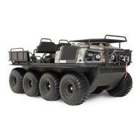
Figure 7-4. Location of the sliders.
Clutch Inspection
Inspect the nylon sliders every 50 hours. The nylon sliders
are mounted in the driven clutch moveable pulley. (Figure 7-
4). When the clutch shifts, the cam moves on the nylon sliders.
Replace the nylon sliders before there is aluminum to aluminum
contact between the cam and the movable pulley. Driven clutch
disassembly is required to replace the nylon sliders properly.
Return the vehicle to an ARGO dealer for service.
7.2.3 DRIVE CHAINS
Roller chain “stretch” results from wear to the chain pins and
bushings because of the loss of lubricant.
To prevent sprocket damage and unnecessary breakdowns,
replace the chains when:
• the chain tensioner can no longer take up the chain slack.
• the chain is rubbing on a frame cross member.
• the chain is seized due to rust and lack of lubrication.
• the chain climbs the sprocket teeth, especially noticeable
when turning.
To remove the Drive Chains:
1. Place the gearshift in the N (neutral) position.
2. Remove the floor pans.
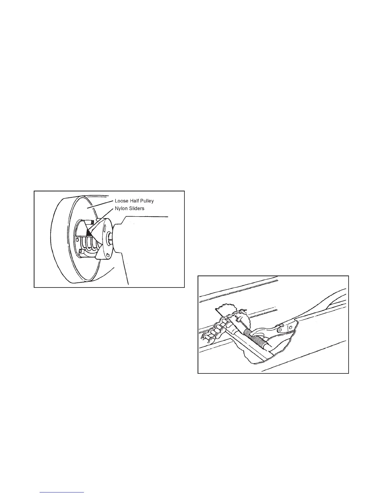
3. Turn the tensioner cam assembly in the direction which
winds up the torsion spring and push the assembly down
as close as possible to the cam follower block in the bot-
tom of the frame. Secure it in this position with a Vice-Grip
10CR as illustrated in Figure 7-6.
4. Roll the vehicle until the connecting link on one of the
chains is visible.
5. Remove the spring clip from the connecting link as shown
in Figure 7-7. Remove the outside plate and tap out the
connecting link. The inside plates will be released when
the connecting link is removed (Figure 7-8).
6. Remove the chain from the vehicle.
7. Repeat steps 4 to 6 until all drive chains are removed.
Figure 7-6. Securing tensioner cam
To install the Drive Chains:
1. Position the drive chain over the slider block and around
the drive sprockets.
2. Pull the ends of the chain together and insert the connect-
ing link as shown in Figure 7-8 and 7-9. When connecting
the RC50-2 chain, insert the inside plates before tapping
the connecting link into position.
 Loading...