32
7.2.4 DRIVE CHAIN TAKE-UP SYSTEM
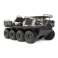
Figure 7-9. Installing the connecting link
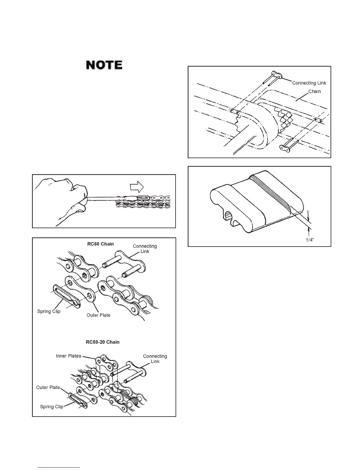
Figure 7-10. Wear groove on the slider block.
The chain tensioning system on all C, R, B, N, S and A models
consists of a torsion spring loaded cam assembly with a slider
block which takes up the slack on the bottom side of all but
the front final drive chains. The AVENGER model utilizes the
same tensioner system as the above models with the addition
of a chain tensioner on the front final drive chains as well. As
the chain wears, the chain tensioning mechanism adjusts semi-
automatically. Under most conditions, the tensioner cam as-
sembly will move to the next step of adjustment simply due to
normal drive system dynamics. Sometimes, however, the cam
assembly can bind due to debris caught in the area. IT IS
VERY IMPORTANT TO CHECK THAT THE CAM ASSEM-
BLY IS PROGRESSING PROPERLY. CHECK FOR PROPER
CHAIN TENSIONER OPERATION AFTER THE FIRST TWO
HOURS OF USE AND THEN EVERY 10 HOURS OF VEHICLE
OPERATION, WHEN THE DRIVE CHAINS ARE BEING LU-
BRICATED. Each step of the cam takes up about 2.5 inches of
chain slack (see Fig. 7-11).
SECTION 7
MAINTENANCE INFORMATION
Use a pair of modified 7R Vice Grips to hold the ends of
the chain together while inserting the connecting link.
Some drive chains have no slack, and replacement of
the connecting link is difficult without this tool. Modi-
fied Vice Grips can be ordered from your ARGO dealer
(ARGO Part No. 658-08) or refer to Appendix 1 for
modification information.
3. Replace the outside plate and spring clip. The open end of
the clip must face rearward when it is on top of the chain.
4. Remove the vice-grips securing the cam assembly in its
lowest position.
5. Repeat steps 1 to 4 until all chains are replaced.
Figure 7-7. Removal of the spring clip.
Figure 7-8. Chain connection link components.
 Loading...