34
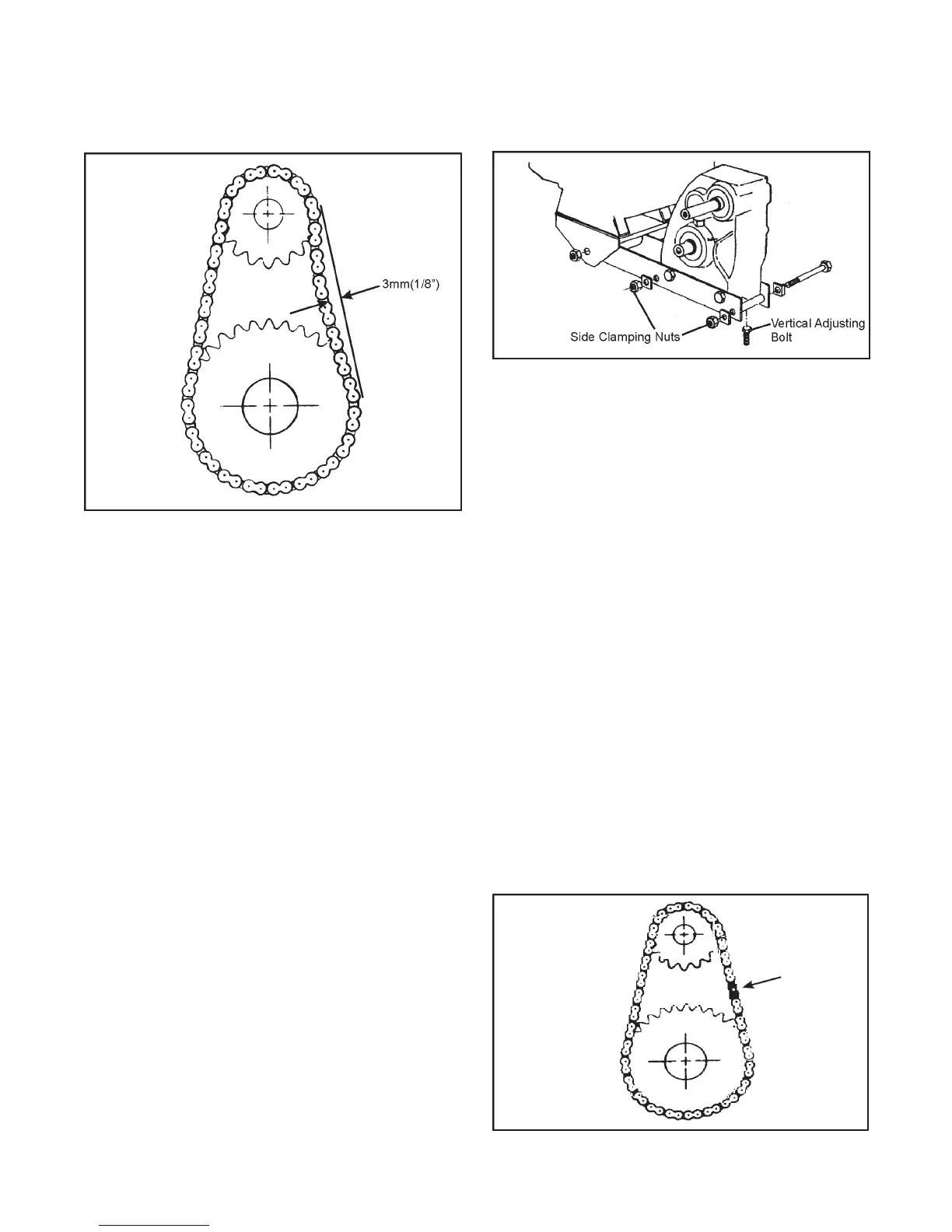
Figure 7-16. Location of power pack clamping nuts
and adjusting bolts
Idler Chain Replacement
Replacement of the idler chains is required if the adjustment
bolt is fully extended and idler chain deflection still exceeds 3
mm (1/8").
To Remove the Idler Chains:
Loosen the power pack clamping nuts and adjusting bolts as
shown in Figure 7-16 and proceed as follows:
1. Place the gearshift in neutral and roll the vehicle until the
connecting link of one of the idler chains is positioned as
shown in Figure 7-17.
2. Remove the spring clip or cotter pins, depending on model,
from the connecting link. Remove the outside plate and
tap out the connecting link. On models that utilize a dou-
ble 40 or 50 drive chain, as the connecting link is removed,
the inside plates will be released (refer to Figure 7-8). Mod-
els with single 60 drive idler chains have no inside plates.
3. Remove the idler chain from the vehicle.
4. Repeat steps 1 to 3 to remove the other idler chain.
Figure 7-17. Position of idler chain link for removal.
SECTION 7
MAINTENANCE INFORMATION
Figure 7-15. Measuring idler chain deflection
To check the idler chain adjustment, push the slack side of the
chain and measure the amount of chain deflection (Figure 7-
15). Adjust the idler chain tension if deflection is more than
3mm (1/8").
Idler Chain Adjustment
1. Remove the firewall from the vehicle as detailed in Section
7.3.1 for the Vanguard and Section 7.4.4 for the Vanguard2,
Bigfoot, Response, Conquest and Avenger models.
2. Loosen the 2 left side clamping nuts with a 15/16" socket
wrench (figure 7-16). Loosen the 3/8" hex nut (117-15)
securing the adjustment support (602-27), just above the
transmission, to the hood frame assembly. (Refer to Sec-
tion 6.0 of the Parts Manual.) Note: Avenger and Frontier
models do not have this adjustment support.
3. Turn the vertical adjustment bolts counter-clockwise to
raise the power pack and tighten the idler chains. The idler
chains are properly adjusted when the deflection meas-
ures 3 mm (1/8"), (Figure 7-15).
4. Tighten the 2 left side clamping nuts securely. Torque to
130ft./lbs. Tighten the adjustable support fasteners with
the rubber bumper (126-88) pressed down firmly onto the
top of the transmission.
 Loading...