38
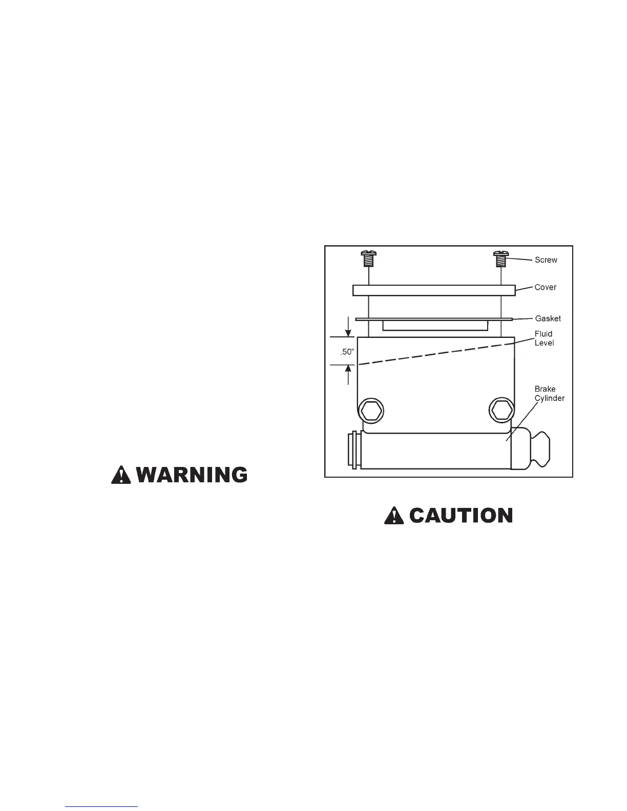
The master cylinders are mounted tilted slightly back. When
adding fluid, fill until the shallowest end of the fluid level in
the well is approximately 1/2" from the top lip of the master
cylinder (Figure 7-24).
If the brake fluid is below this level:
1. Add only fresh clean SILICONE - DOT 5 BRAKE FLUID
(ARGO Part No. 126-19) to the correct level.
2. Replace the cover on each master cylinder, making sure
the rubber gaskets are properly seated before tightening
the cover screws. Tighten snug by hand only.
Figure 7-24. Hydraulic brake cylinder and fluid level
Do not overfill the brake master cylinders. Overfilling
can cause seal damage.
Use only SILICONE - DOT5 BRAKE FLUID. Other brake
fluid may not be compatible with ARGO brake compo-
nents and operating temperatures. Use of other fluids
will void the warranty.
7.4.3 CHANGING BRAKE FLUID
The inherent stability of Silicone DOT 5 Brake Fluid reduces
the need for frequent brake fluid replacement. Inspect the
fluid for degradation (discolouration or particles) during nor-
mal fluid level inspections. If discolouration has occurred, the
brake fluid system should be drained, flushed and refilled with
fresh brake fluid. If particles are evident in the fluid, drain the
system, overhaul the master cylinder and the brake caliper
before flushing and refilling. An ARGO dealer will preform
these operations for you.
SECTION 7
MAINTENANCE INFORMATION
1. Pull the left steering lever back.
2. While holding the lever, lift the spring loaded brake lever
until it contacts the pin in the steering lever.
3. Release the steering lever, allowing the holding brake lever
to lock the left brake on.
4. If the steering lever grip is approximately 18 cm (7") from
the dash, the holding brake system is correctly adjusted.
5. If the distance from the dash is greater, refer to Section
7.3.4 STEERING LEVER ADJUSTMENT to properly set
the left lever.
To re-install the firewall:
1. Pull both steering levers back, away from the dash as far as
possible.
2. Position the firewall in the driving compartment.
3. Insert the bottom edge of the firewall in front of the retain-
ing bracket.
4. Move the top of the firewall forward into position, aligning
the two release catches.
5. Turn the two release catches clockwise 1/4 turn to lock.
Do NOT operate the ARGO with the firewall removed.
7.4 HYDRAULIC BRAKES - VANGUARD2, BIGFOOT,
RESPONSE, CONQUEST, CONQUEST 6X6, FRONTIER &
AVENGERS
7.4.1 GENERAL
Although the hydraulic brake system is self adjusting, the
following require periodic attention:
7.4.2 BRAKE FLUID LEVEL
After every 50 hours of operation, check the brake fluid level
by removing the master cylinder covers.
IMPORTANT
Thoroughly clean the master cylinder cover and surround-
ing area before removal.
 Loading...