40
7.4.6 BRAKE PLUNGER ADJUSTMENT (All V, H, F, C, R,
B, A and N Models)
IMPORIMPOR
IMPORIMPOR
IMPOR
TT
TT
T
ANTANT
ANTANT
ANT
It is critical that the master cylinder pistons are ad-
justed properly when the steering handlebars are in
the centred position. Overheating of the brake system
could occur due to the piston being adjusted too far in.
This could cause a drag on the system and a possible
brake lockup. On the other hand, the piston being ad-
justed too far out increases the distance the piston is
required to travel to provide brake pressure. This can
result in the steering arm contracting and/or bending
the plunger pin guide tab resulting in compromised
system operation.
1. Remove the firewall.
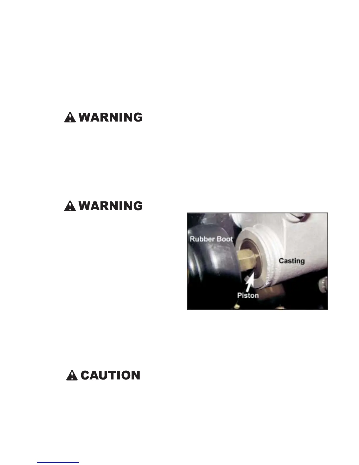
2. Pull back the rubber boot at both master cylinder plunger
pins and check each piston location relative to the face of
the master cylinder casting as illustrated in figure 7-27.
Use a straight edge against the face of the casting to en-
sure the piston is between zero and 0.5 mm depth in the
master cylinder.
Figure 7-27. Location of piston.
3. If adjustment is needed, loosen the jam nut and thread the
adjustable plunger pin either in or out as necessary.
4. Loosen the set screw on each of the plunger pin collars
and push them up against the plunger pin guide tabs.
Apply Loctite # 242 to the set screw threads and re-secure
the set screws.
7.4.7 BRAKE COOLING SYSTEM (All V, H, C, R, B, A,
and N Models)
Some vehicles with hydraulic brakes have a 12 volt fan forcing
cool air from outside the engine compartment onto the brake
components to protect the system from overheating. Over-
heating can damage the hydraulic brake components. Make
SECTION 7
MAINTENANCE INFORMATION
3. Push in the top of firewall up against the tabs located on
the left and right hand side of the dash support.
4. Line up the firewall release catch with the mounting clasp
on the frame and turn clockwise 1/4 turn to lock.
5. Reinstall the shifting lever boot.
Do NOT operate the ARGO with the firewall removed.
7.4.5 HAND BRAKE ADJUSTMENT (All V, H, F, C, R, B, A
and N models)
The brake system has been factory adjusted to ensure proper
braking effectiveness. However, before the vehicle is used
for the first time, and after every 25 hours of operation, the
adjustment of the brake must be inspected.
The use of an improperly adjusted brake is a serious
hazard, and could lead to vehicle damage or personal
injury.
The lockable holding portion of the brake system is not
a parking brake, and therefore is not designed to hold
the vehicle in place for long periods of time. The hold-
ing brake is for short term use only.
When parking on an incline, engage the holding brake
lever pin, leave the vehicle in gear, turn the engine off
and block the vehicle's wheels.
The hand brake lever should be adjusted such that when
squeezed and locked into position, it is capable of holding the
vehicle from rolling on a grade. It should also ensure a good
braking response when applied to stop the vehicle during
normal operation. Loosen the locking jam nut at the adjust-
ment end of the brake cable (near the brake plunger cams) and
thread the adjustment "OUT" to decrease brake lever travel
and provide more braking action or "IN" to increase brake
lever travel and less braking action. Retighten the jam nut.
If the holding brake system is too tight, excessive pres-
sure in the brake system will damage the seals.
 Loading...