13
Table 1-13 Indoor Unit Tubing Connection (
1
,
2
...
n–1
)
(mm)
ø15.88
ø9.52
Unit: mm
ø6.35
ø12.7
Gas tubing
(mm)
Liquid tubing
Indoor unit type 22 28 36 56 73 106 140
ø9.52
ø15.88
ø9.52
ø12.7
(mm)
(mm)
–
7.1
(2.5 hp)
7.1
(
2.5
hp)
15.5
(6 hp)
Below kW
Over kW
Total capacity
after distribution
Tubing size
Gas tubing
Liquid tubing
hp = horsepower
Unit: mm
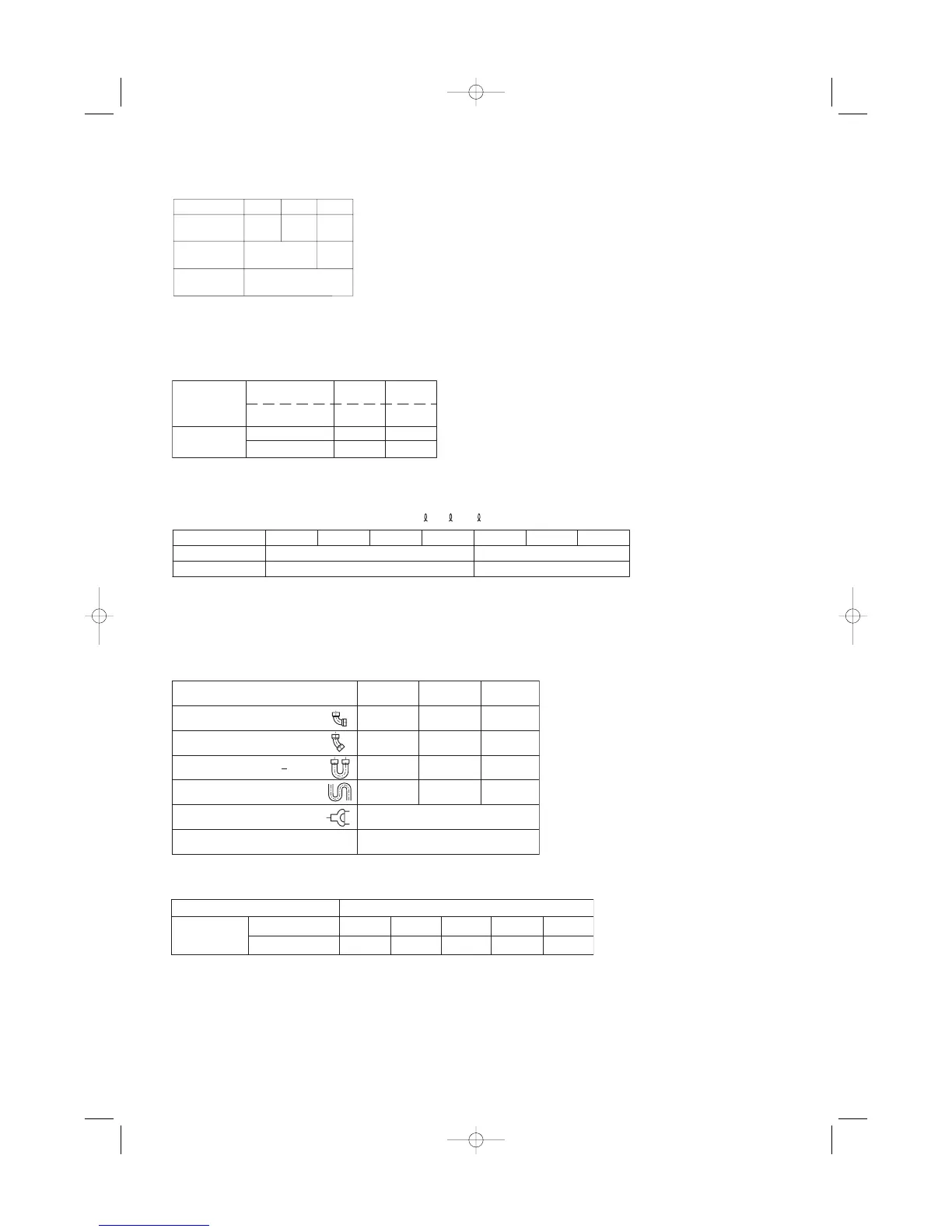
1-5. Tubing Size
Table 1-11 Main Tubing Size (LA)
ø19.05
6
Unit: mm
15.5
14.0
5
ø9.52
ø15.88
4
11.2
kW
System
horsepower
Gas tubing
(mm)
Liquid tubing
(mm)
Table 1-12 Main Tubing Size After Distribution (LB, LC...)
Note: In case the total capacity of connected indoor units exceeds the total capacity of the outdoor units, select the main
tubing size for the total capacity of the outdoor units.
Note: When only one indoor unit is connected to a 6-hp outdoor unit, connect ø19.05 gas tubing up to just before the indoor
unit, then use a socket or similar device (field supply) to change the tube diameter to ø15.88 and connect the gas tube
to the indoor unit.
Material O
Copper tubing
Outer diameter 6.35 9.52 12.7 15.88
Wall thickness 0.8 0.8 0.8 1.0
1.0
19.05
Table 1-15 Required Copper Tubing Dimensions Unit: mm
Gas tubing size (mm)
90°
elbow
45°
elbow
U-shape tube bend (R60 100
mm)
Trap bend
12.7
0.30
0.23
0.90
2.30
15.88
0.35
0.26
1.05
2.80
19.05
0.42
0.32
1.26
3.20
Y-branch distribution joint Equivalent length conversion not needed.
Ball valve for service Equivalent length conv
ersion not needed.
1-6. Straight Equivalent Length of Joints
Design the tubing system by referring to the following table for the straight equivalent length of joints.
Table 1-14 Straight Equivalent Length of Joints
06-065 Mini ECO-i II for ARGO 2/8/06 4:37 PM Page 13