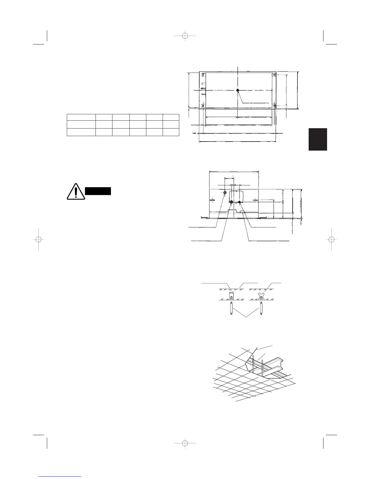
Suspension bolt pitch B
Ceiling opening dimension A
Suspension bolt pitch
Ceiling opening dimension
Center of panel
and ceiling
opening
30
40
70
20 600
530
640
C
ED
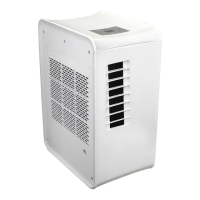
Drain outlet
Refrigerant
connection outlet
(gas tube)
Refrigerant connection
outlet (liquid tube)
Outlet for power cord,
inter-unit wiring &
optional cord
3508
115195
220
29060 – 65
110
600
7030
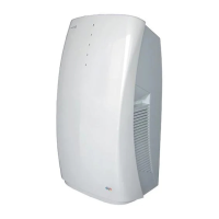
Hole-in-anchor
Hole-in-plug
Concrete Insert
Suspension bolt (M10 or 3/8")
(field supply)
2-Way Air Discharge Semi-Concealed Type
(AS2S Type)
3-9. Suspending the Indoor Unit
(1) Follow the diagrams to make the holes in the ceil-
ing.
Table 3-2
(2) Depending on the ceiling type:
Insert suspension bolts as shown in Fig. 3-36
or
Use existing ceiling supports or construct a suitable
support as shown in Fig. 3-37.
It is important that you use
extreme care in supporting
the indoor unit from the ceil-
ing. Ensure that the ceiling
is strong enough to support
the weight of the unit.
Before hanging the unit, test
the strength of each
attached suspension bolt.
(3) Cut the ceiling material, if necessary. (Refer to
Figs. 3-34 and 3-35, and Table 3-2.)
ABCDE
22, 28, 36, 56 1,020 920 840 400 440
73 1,320 1,220 1,140 550 590
Fig. 3-37