Drain hose
(supplied)
(not supplied)
(not supplied)
Packing (supplied)
VP-25
Align the hose band with end of the
hose, and tighten so that it does not
contact the bead.
Drainage check
section on drain port
(transparent)
Hard PVC
socket VP-25
Hard PVC
pipe
PVC adhesive
Bead
Vinyl clamps
Drain insulator (supplied)
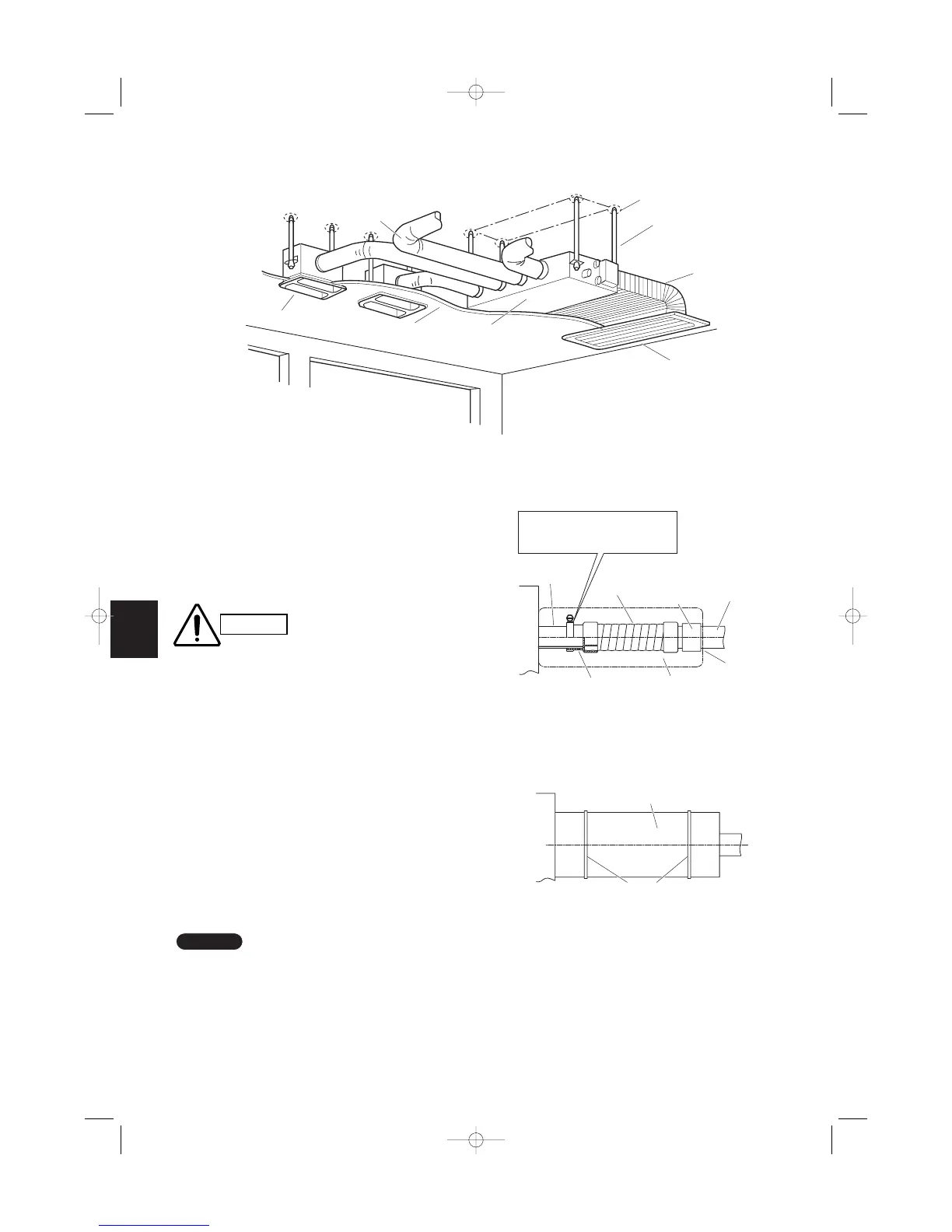
3-32. Installing the Drain Piping
(1) Prepare standard hard PVC pipe (O.D. 32 mm) for
the drain and use the supplied hose band to pre-
vent water leaks.
The PVC pipe must be purchased separately.
The transparent drain part on the unit allows you
to check drainage. (Fig. 3-105a)
Do not use adhesive at the
drain connection port on
the indoor unit.
Insert the drain pipe until it
contacts the socket, as
shown in the figure at right,
then secure it tightly with
the hose band.
Do not use the supplied
drain hose bent at a 90°
angle. (The maximum per-
missible bend is 45°.)
Tighten the hose clamps so
their locking nuts face
upward. (FIg. 3-105a)
(2) After connecting the drain piping securely, wrap
the supplied packing and drain pipe insulator
around the pipe, then secure it with the supplied
vinyl clamps. (Fig. 3-105b)
Make sure the drain pipe has a downward gradient
(1/100 or more) and that there are no water traps.