AS2S
40
Fig. 3-38
Fig. 3-39
Fig. 3-40
Fig. 3-41
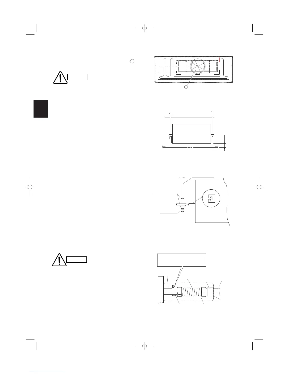
(5) If the system requires fresh air to be drawn into
the unit, cut and remove the insulation (both exter-
nally and internally) at the location shown as
in Fig. 3-38.
3-10. Placing the Unit Inside the Ceiling
(1) When placing the unit inside the ceiling, determine
the pitch of the suspension bolts.
Tubing must be laid and connected inside the ceil-
ing when suspending the unit. If the ceiling is
already constructed, lay the tubing into position for
connection to the unit before placing the unit
inside the ceiling.
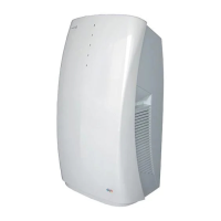
(2) Thread the 3 hexagonal nuts and 2 washers (field
supply) onto each of the the 4 suspension bolts as
shown in Fig. 3-40. Use 1 nut and 1 washer for the
upper side, and 2 nuts and 1 washer for the lower
side, so that the unit will not fall off the suspension
lugs.
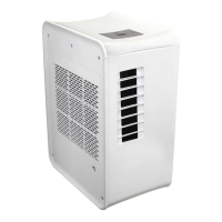
(3) The distance between the unit and the opening in
the ceiling and the distance between the bottom
surface of the ceiling and the bottom surface of the
flange of the unit should follow the dimensions
given in Figs. 3-39. Use the supplied installation
gauge to check.
3-11. Installing the Drain Piping
(1) Prepare a standard hard PVC pipe (O.D. 32 mm)
for the drain and use the supplied drain hose and
hose band to prevent water leaks. The PVC pipe
must be purchased separately.
When doing this, leave a gap between the drain
socket and the PVC pipe to allow the drainage to
be checked. The unit’s transparent drain port
allows you to check the drainage. (Fig. 3-41)
Do not use adhesive at the drain connection port
on the indoor unit.
Insert the drain pipe until it contacts the socket,
as shown in the figure at right, then secure it
tightly with the hose band.
Tighten the hose clamps so their locking nuts
face upward. (Fig. 3-41)
Do not use the supplied drain hose bent at a 90°
angle. (The maximum permissible bend is 45°.)
Unit: mm