14
1-7. Additional Refrigerant Charge
Additional refrigerant charge amount is calculated from the liquid tubing total length as follows.
Table 1-16 Amount of Refrigerant Charge Per Meter, According to Liquid Tubing Size
Liquid tubing size Amount of refrigerant
charge/m (g/m)
ø6.35 26
ø9.52 56
Required amount of charge = (Amount of refrigerant
charge per meter of each size of liquid tube × its tube
length) + (...) + (...)
*Always charge accurately using a scale for weighing.
Table 1-17 Refrigerant Charge Amount at Shipment (for outdoor unit)
1-8. System Limitations
Table 1-18 System Limitations
Number of max. connectable indoor units
Outdoor units (Type)
04 05 06
6 8 9
Max. allowable indoor/outdoor capacity ratio
50 – 130%
Heat pump unit
AES04MMIH
3.5
AES05MMIH
3.5
AES06MMIH
3.5
(kg)
1-9. Tubing Length
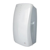
Table 1-19 Ranges that Apply to Refrigerant Tubing Lengths and to Differences in Installation Heights
R410A distribution joint
DDVI16 (for indoor unit)
Note: Do not use commercially available T-joints for the liquid tubing.
H2
LD
L1
L2
LCLB
LA
* Be sure to use special R410A distribution joints (DDVI: purchased separately)
for outdoor unit connections and tubing branches.
Main tube of unit
1st branch
Unit distribution tube
1
2 3
n-1
n
L3
H1
Items Marks Contents Length (m)
L1 Max. tubing length
Actual length
150
Equivalent length
175
L (L2 – L3)
Difference between max. length and min.
40
length from the No.1 distribution joint
1
,
2
~
n
Max. length of each distribution tube 30
1
+
2
+~
n–1
Total max. tubing length including length of
200
each distribution tube (only liquid tubing)
H1
When outdoor unit is installed higher than indoor unit
50
When outdoor unit is installed lower than indoor unit 40
H2 Max. difference between indoor units
15
L = Len
ht
Allowable tubing
length
>
>
Allowable elevation
differenc
e
>
>
>
>
>
>
+L1
Select the installation location so that the length and size of refrigerant tubing are within the allowable range shown
in the figure below.
06-065 Mini ECO-i II for ARGO 2/8/06 4:37 PM Page 14