Install wiring correctly
(incorrect wiring will dam-
age the equipment).
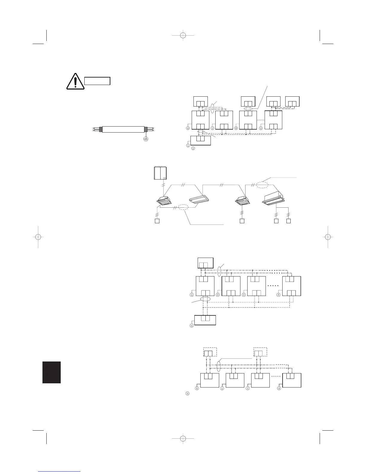
Use shielded wires for remote control wiring and
ground the shield on both sides. (Fig. 6-3) Other-
wise misoperation due to noise may occur.
Fig. 6-3
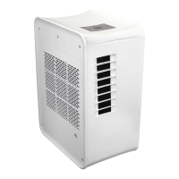
Fig. 6-4
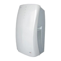
6-3. Wiring System Diagram for Group Control
This diagram shows when several units (maximum of
8) are controlled by a remote controller (master unit).
In this case, a remote controller can be connected at
any indoor unit.
Wiring procedure
Wire according to the right diagram:
Each successive unit will respond at 1-second
intervals following the order of the group address
when the remote controller is operated.
Group control using 2 remote controllers
It does not matter which of the 2 remote controllers
you set as the main controller.
When using multiple remote controllers (up to 2 can
be used), one serves as the main remote controller
and the other as the sub-remote controller.