ACS
52
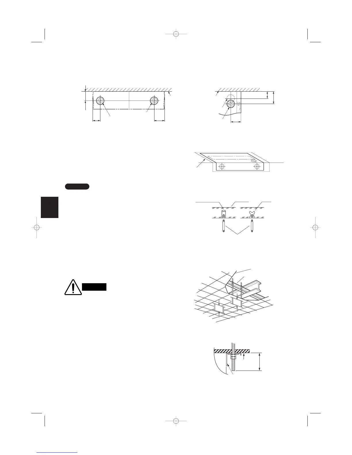
(4) Wall and ceiling side opening position
90
145
135
125
155
90
*
Figure shows view from front Figure shows view from top
φ100 wall side opening
(for left-side drain hose)
φ100 wall side opening
φ100 ceiling opening
φ100 ceiling opening
Wall
Ceiling
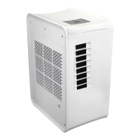
Full-scale
installation diagram
Wall
Ceiling
Fig. 3-84
Fig. 3-83
Fig. 3-85
3-26. Suspending the Indoor Unit
(1) Place the full-scale diagram (supplied) on the ceil-
ing at the spot where you want to install the indoor
unit. Use a pencil to mark the drill holes.
(Fig. 3-84).
Since the diagram is made of paper, it may shrink or
stretch slightly because of high temperature or humid-
ity. For this reason, before drilling the holes maintain
the correct dimensions between the markings.
(2) Drill holes at the 4 points indicated on the full-
scale diagram.
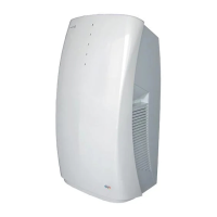
(3) Depending on the ceiling type:
a) Insert suspension bolts as shown in Fig. 3-85.
or
b) Use existing ceiling supports or construct a suit-
able support as shown in Fig. 3-86.
It is important that you use
extreme care in supporting
the indoor unit from the ceil-
ing. Ensure that the ceiling
is strong enough to support
the weight of the unit. Before
hanging the ceiling unit, test
the strength of each
attached suspension bolt.
(4) Screw in the suspension bolts, allowing them to
protrude from the ceiling as shown in Figs. 3-85
and 3-86. The distance of each exposed bolt must
be of equal length within 50 mm. (Fig. 3-87)
Hole-in-anchor
Hole-in-plug
Concrete Insert
Suspension bolt (M10 or 3/8")
(field supply)
Ceiling tiles
Ceiling support
A
A
unit
Ceiling
surface
Fixture
Within
50 mm
06-065 Mini ECO-i II for ARGO 2/8/06 4:37 PM Page 52