84
Fig. 7-8
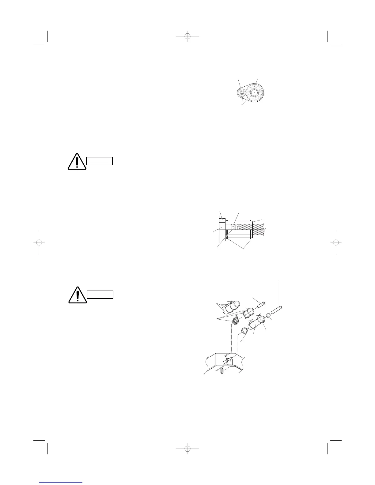
Fig. 7-9
7-3. Insulating the Refrigerant Tubing
Tubing Insulation
Thermal insulation must be applied to all unit tub-
ing, including distribution joint (purchased sepa-
rately).
* For gas tubing, the insulation material must be
heat resistant to 120°C or above. For other tubing,
it must be heat resistant to 80°C or above.
Insulation material thickness must be 10 mm or
greater.
If the conditions inside the ceiling exceed DB 30°C
and RH 70%, increase the thickness of the gas
tubing insulation material by 1 step.
Taping the flare nuts
Wind the white insulation tape around the flare nuts at
the gas tube connections. Then cover up the tubing
connections with the flare insulator, and fill the gap at
the union with the supplied black insulation tape.
Finally, fasten the insulator at both ends with the sup-
plied vinyl clamps. (Fig. 7-8)
Insulation material
The material used for insulation must have good insu-
lation characteristics, be easy to use, be age resis-
tant, and must not easily absorb moisture.
After a tube has been insu-
lated, never try to bend it
into a narrow curve
because it can cause the
tube to break or crack.
Two tubes arranged together
If the exterior of the outdoor
unit valves has been finished
with a square duct covering,
make sure you allow sufficient
space to use the valves and to
allow the panels to be
attached and removed.
Fig. 7-7