ASBS
35
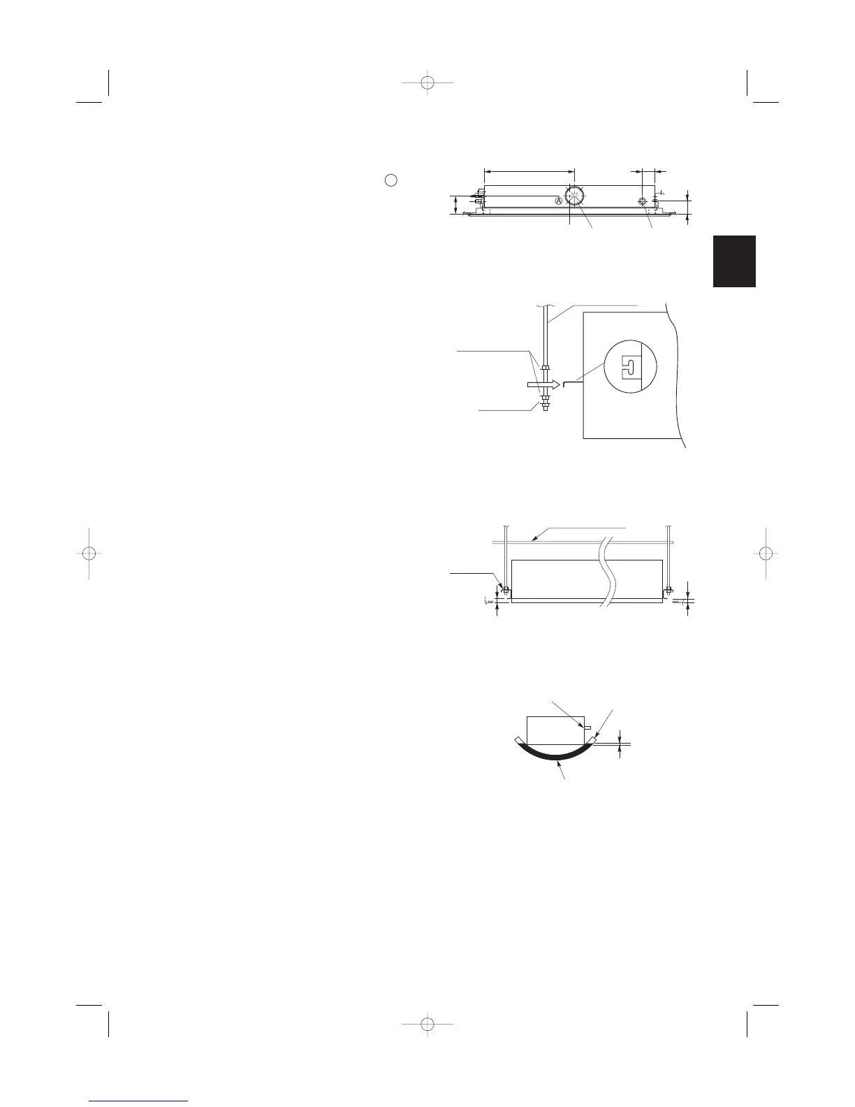
(5) If the system requires fresh air to be drawn into
the unit, cut and remove the insulation (both exter-
nally and internally) at the location shown as
in Fig. 3-22.
3-6. Placing the Unit Inside the Ceiling
(1) When placing the unit inside the ceiling, determine
the pitch of the suspension bolts using the sup-
plied full-scale installation diagram. (Fig. 3-17)
Tubing must be laid and connected inside the ceil-
ing when suspending the unit. If the ceiling is
already constructed, lay the tubing into position for
connection to the unit before placing the unit
inside the ceiling.
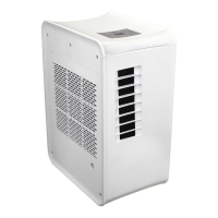
(2) Thread the 3 hexagonal nuts and 2 washers (field
supply) onto each of the the 4 suspension bolts as
shown in Fig. 3-23. Use 1 nut and 1 washer for the
upper side, and 2 nuts and 1 washer for the lower
side, so that the unit will not fall off the suspension
lugs.
(3) The indoor unit should be suspended from the
suspension bolts (Fig. 3-23) so that the distance
between the bottom of the suspension lug and the
bottom surface of the ceiling is 30 to 40 mm.
(Fig. 3-24)
Clearance between the indoor unit and the bottom
surface of the ceiling is adjustable after the ceiling
panel is attached to the unit.
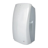
(4) The unit should be adjusted using water level or
as shown in Fig. 3-25 so that the drain pipe side is
slanted 5 mm lower than the opposite side.
(5) After completing the adjustment of the clearance,
fasten all upper and lower suspension nuts tightly.