REM
81
6-6. Wiring the Remote Controller
<Flush Mounting>
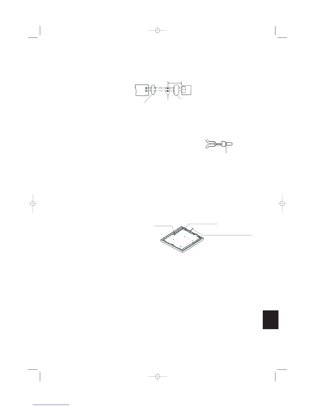
Connection diagram
Use 0.5 mm
2
– 2 mm
2
wires.
(1) Strip the insulation to approximately 14 mm from
the ends of the wires that will be connected.
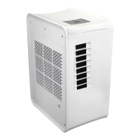
(2) Twist together the 2 wires and create a crimp con-
nection at the wire joint.
(3) If a special crimping tool is not used, or if the con-
nection is soldered, insulate the wires using insu-
lation tape.
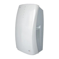
Use the remote controller cord (optional) for remote
controller wiring.
(1) Disconnect the lead wire that is wound around the
lead wire anchor on the remote controller unit. Dis-
connect the connector and connect the remote
controller cord (optional) to the connector on the
remote controller unit. Insert the remote controller
cord (optional) into the groove and bend it into the
correct shape, then wind it around the lead wire
anchor.
(2) If the remote controller cord (optional) is used,
refer to the installation manual that is provided
with the cord.