REM
79
Cautions on group control
Group control within the same refrigerant tub-
ing system is recommended.
[Tubing system which is NOT recommended]
<Example 1> In the MULTISET system, group control
extending over tubing systems becomes
impossible to set, which means the
indoor units cannot operate.
While Group 4 is in heating operation, if later Group 3
begins cooling operation, indoor units 1, 2 of Group 3
can be operated, but the indoor units 3-6 of Group 4
cannot operate.
NOTE
3
45621
21321321
Indoor Units
Outdoor units
Group 4
Group 3 Group 2 Group 1
Remote
controller
Group address
Tubing system 1
Tubing
system 2
TIMER
TMNL.
RCU
TMNL.
RCU.ADR
RCU.Main
RCU.Sub
RCU.CK
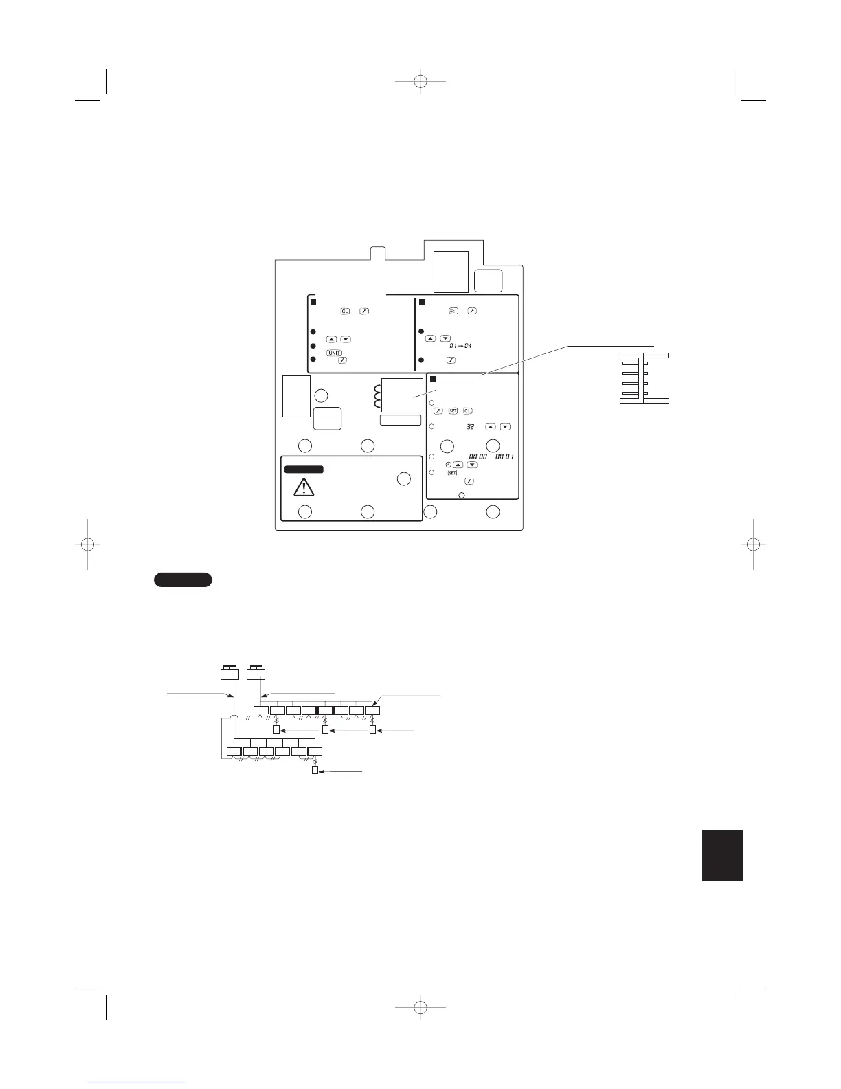
To Service Technicians
To display the sensor temperature:
WARNING
To avoid an electric shock hazard,
DO NOT touch any ter-
minal on the Printed Cir-
cuit Board with a metal rod, a
screwdriver edge or bare hand
when power
is supplied.
Press both and buttons on the
remote controller for more than 4 seconds
together.
Change the sensor address (CODE NO.)
with / (SET TEMP) buttons.
Select the UNIT NO. that you want to call
with button.
Press the button to finish service mode.
To display the trouble history:
Press both and buttons on the
remote controller for more than 4 seconds
together.
Change the alarm message:
/ (SET TEMP) buttons
CODE NO.
Press the button to finish service
mode.
On the remote controller, press
+ + at the same time for
more than 4 seconds.
Set CODE No. with /
(SET TEMP) button.
Set DATA from to
with / (TIMER) button.
Press
Finally, Press
(New) (Old)
Changing method for room
temperature sensor (from Indoor
unit to RCU)
1
2
3
4
Remote Controller (Main)
Remote Controller (Sub)
Remote controller
address connector
Setting the main and sub remote controllers
1. Set one of the 2 connected remote controllers as the main remote controller.
2. On the other remote controller (sub-remote controller), switch the remote controller address connector on the
rear of the remote controller PCB from Main to Sub. When the connector has been switched, the remote con-
troller will function as the sub-remote controller.
The sub-remote controller will also operate when connected to the indoor unit (indoor unit 2 or 3).
Fig. 6-6
06-065 Mini ECO-i II for ARGO 2/8/06 4:37 PM Page 79