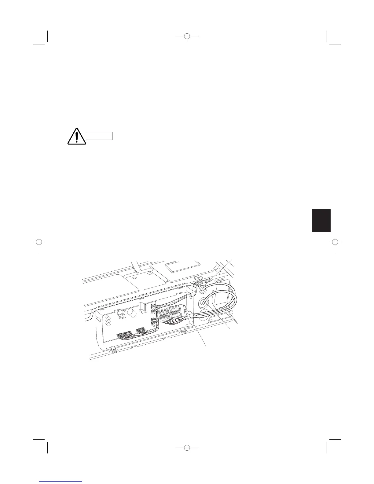
* Insert the remote controller
wiring into the electrical
component box from the
inlet port as shown in the
figure. This is done
regardless of whether the
wiring was inserted from
the top, rear, or left side of
the main unit.
Remote controller wiring inlet port
Power, inter-unit wiring
Power, inter-unit wiring, remote
controller wiring inlet port
Clamp
How to carry out power supply wiring
(1) Wiring connection ports
The power inlet ports are located at the rear and top.
The remote controller wiring inlet ports are located at
the rear and top (for use with the wired remote con-
troller).
For details, refer to Fig. 3-94a. For the method used
to insert the wiring, refer to the figure below.
(Fig. 3-97)
(2) How to carry out wiring
Open the knock-out hole on the rear or top of the
main unit. Attach the supplied rubber grommet and
pull the power wiring into the main unit.
Feed the wiring into the wiring inlet port on the
electrical component box. Connect the wiring to the
terminal plate and fasten in place with the supplied
clamp.
Perform electrical and grounding work in accor-
dance with the package A/C power specifications,
and following local electrical codes and regulations.
When removing the fasten-
ing bracket from the cover
of the electrical component
box, use caution to avoid
dropping the bracket.
Fig. 3-97



 To Next Page