Chapter 4: Cabling the Modular Switch DC Power Adapter Installation for PWR-2700-DC-R
Quick Start Guide: 7500N Series Modular Switches 31
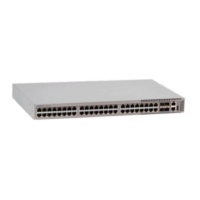
Step 3 Remove the flange locking nuts from each of the terminal studs.
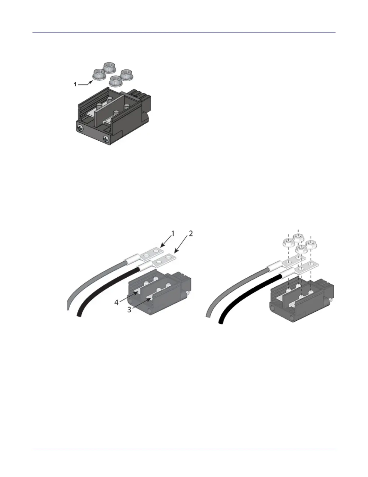
Step 4 Secure each power cable lug to the terminal studs with the flange locking nuts.
• Attach the positive (+) DC source power cable lug to the RTN (return) terminal.
• Attach the negative (–) DC source power cable lug to the –48V (input) terminal.
• Torque the four flange locking nuts to 2.7 N-m (24 in.-lbs.).
1 Flange locking nuts
1 Compression lugs 3 -48V
2 Compression lugs 4 RTN