36 Quick Start Guide: 7500N Series Modular Switches
Connecting Supervisor Cables Chapter 4: Cabling the Modular Switch
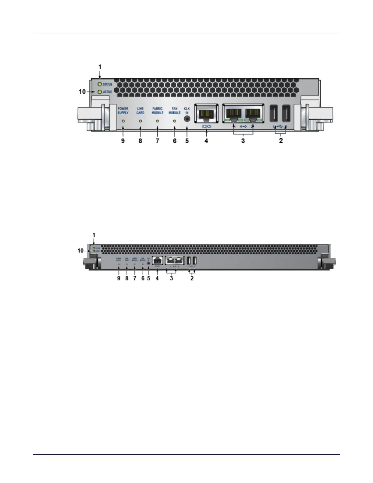
Figure 4-7: Supervisor DCS-7500E-SUP 2
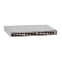
Figure 4-8: Supervisor DCS-7516-SUP
• Console (Serial) Port: Connect to a PC with RJ-45 to DB-9 serial adapter cable. Default switch
settings include:
• 9600 baud
• No flow control
• 1 stop bit
• No parity bits
• 8 data bits
The DCS-7516-SUP supervisor cards must be installed in one of the two slots designated for them in
the DCS-7516N switch as shown in Figure 4-9.
1 Status LED 5 Clock input port (optional) 9 Power supply status LED
2 USB ports 6 Fan module status LED 10 Active LED
3 Ethernet management
ports
7 Fabric module status LED
4 Serial console port 8 Linecard status LED
1 Status LED 5 Clock input port (optional) 9 Power supply status LED
2 USB ports 6 Fan module status LED 10 Active LED
3 Ethernet management
ports
7 Fabric module status LED
4 Serial console port 8 Linecard status LED



 To Next Page