Appendix D: Rear Panel
Quick Start Guide: 7500N Series Modular Switches 61
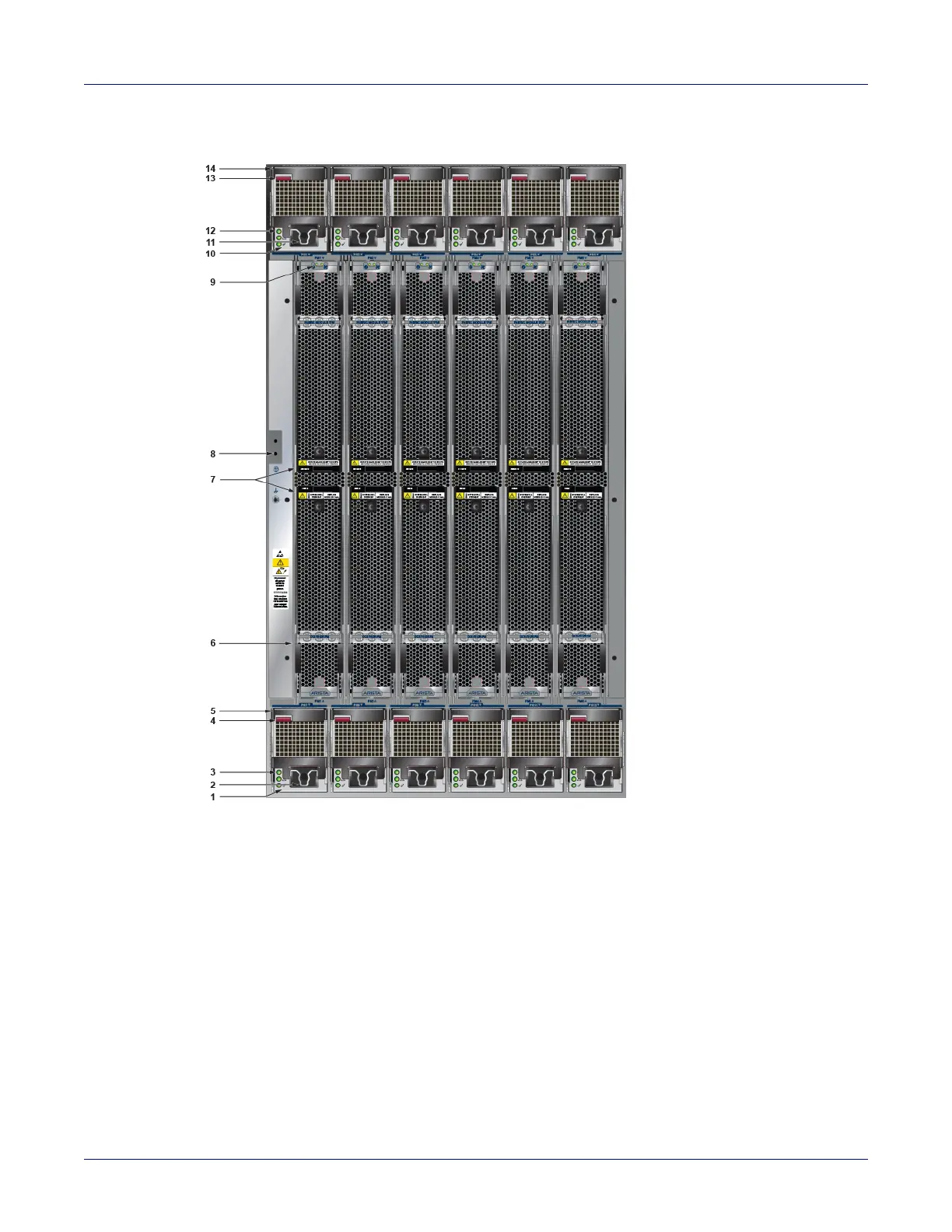
Figure D-3: DCS-7512N rear panel (fully populated)
1 PSU bottom row (PS7) 6 Fabric module 11 Power cord clip (optional)
2 Power cord clip (optional) 7 Fabric module ejector handles 12 Status LEDs (PS1)
3 Status LEDs (PS7) 8 Chassis ground (secondary) 13 Ejector button
4 Ejector button 9 Fabric module status LEDs 14 Release lever
5 Release lever 10 PSU top row (PS1)



 To Next Page