installation &
operating instructions
Design Envelope 4200h & 4280
End Suction Horizontal Pumping Units
10
2.1.2 start / stop of pump
The number of starts/stops via the mains voltage must not
exceed one-time per minute.
If a higher number of starts/stops is required then the start/
stop digital input must be used (mains voltage directly
connected). This is the preferred method of starting and
stopping Pumps.
The three phase mains must be isolated before performing
maintenance of the pump.
2.1.3 additional motor protection
With the exception of supply fuses / mcb’s to protect
the installation (for over-current and short-circuit
protection), no additional overload or over-tempera-
ture protection is required (i.e. thermal overloads). Protection
features include:
• Mains phase loss
• Over voltage
• Under voltage
• Electronic thermal motor protection
• Short circuit on motor terminals
• Ground fault on motor terminals
• Over temperature
2.1.4 motor thermal protection and
derating
The Design Envelope motors are thermally protected in case
limits are exceeded (140°c), another protection is provided
thought the drive.
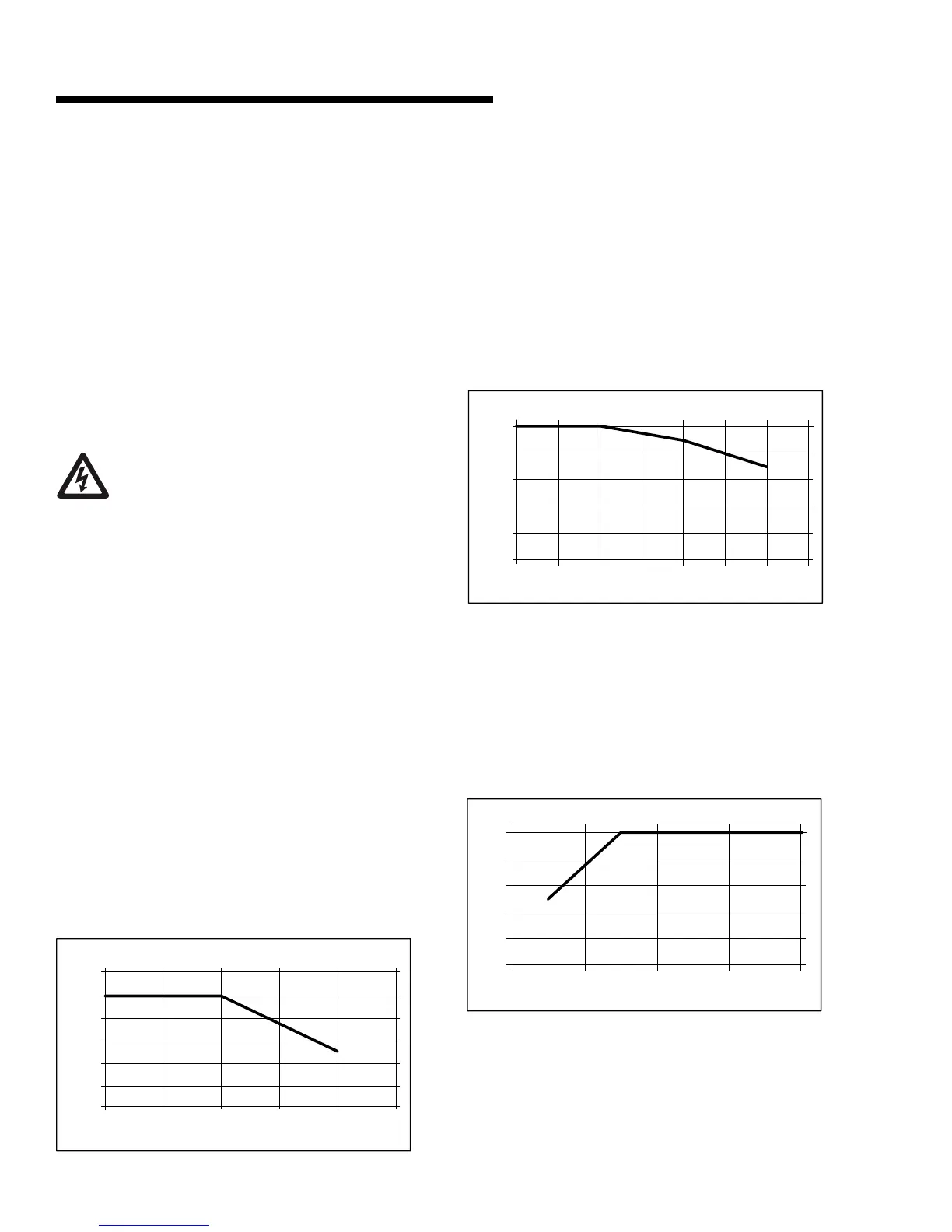
a derating for ambient temperature
The ambient temperature (tamax) is the maximum tempera-
ture allowed.
If the motor is operated at temperatures above 104°f (40°c),
a derating of the continuous output current is necessary.
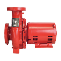
b derating for air pressure
Below 1000 m altitude no derating is necessary. Above 1000
m the ambient temperature (ta) or max. rated output cur-
rent (in) must be de-rated in accordance with the following
diagram.
See the below diagram for derating of output current versus
altitude at ta = Max. 104°f (40°c)
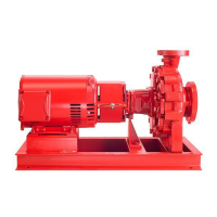
c derating for running at low speed
When a centrifugal pump or a fan is controlled by a 4200h
& 4280 Motor, it is not necessary to reduce the output at
low speed because the load characteristic of the centrifugal
pumps/ fans, automatically ensures the necessary reduction.
The 4200h & 4280 Permanent Magnet motors running con-
stant load torque applications continuously at low speed must
be de-rated (see diagram) or an independent fan must be used.
in the Permanent Magnet motors all control terminals are sup-
plied from or in connection with extra low voltage (pelv).
The components that make up the electrical isolation, as de-
scribed below, also comply with the requirements concerning
higher isolation and the relevant test as described in en 50178.
The galvanic isolation can be shown in three locations (see
drawing below),namely:
0
20
40
60
80
100
0500 1000 1500 2000 2500 3000 3500
ratedtorque [%]
altitude[m]
deratingforair pressure
0
20
40
60
80
100
120
20 30 40 50 60 70
outputcurrent
tambient[°c]
deratingforambienttemperature
0
20
40
60
80
100
010002000300
000
ratedspeed[rpm]
deratingforrunningatlowspeed