installation &
operating instructions
Design Envelope 4200h & 4280
End Suction Horizontal Pumping Units
17
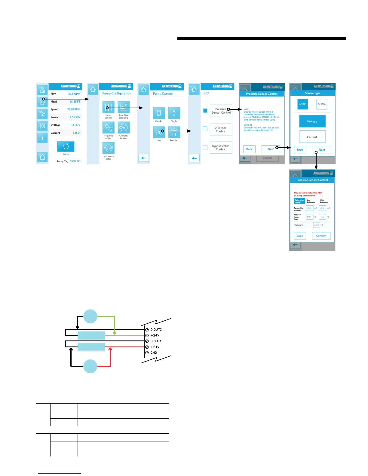
c setting the differential pressure (dp) sensor through lcd
Set the current\ voltage DP sensor setting:
• Set Sensor Signal Intervals
• Set Sensor Pressure range
• Set desire zone pressure
• Click Confirm
2.3.6 digital output
If either of the digital outputs are to be used for voltage dif-
ferential, a 500 ohm resistor (supplied by others) must be con-
nected between the respective digital output and the 24VEXT
terminal. Refer to fig 2.3.6
fig 2.3.6
2.3.7 relay output
J5 & J8 for Relay output
j8
n.o. 2 Relay n.o.
n.c. 2 Relay n.c.
com2 Relay 2A 250Vac
j5
n.o. 1 Relay n.o.
n.c. 1 Relay n.c.
com 1
Relay 2A 250Vac
2.3.8 supply voltage
The supply voltage details can be found on the 4200h &
4280 nameplate. Please ensure that the unit is suitable for the
electrical supply on which it is to be used. The mains supply for
Design Envelope pumps is as follows:
1 × 200-230v ± 10% ,
3 × 200-230v ± 10% ,
3 × 380-480v ± 10%,
3 × 575-600v ± 10%
Frequency - 50/60Hz
2.3.9 supply fusing
Branch circuit protection
in order to protect the installation against electrical and fire
hazard, all branch circuits in an installation, switch gear, ma-
chines etc., must be short-circuit and over-current protected
according to the national/international regulations. Please refer
to section 8.0 (Fuse and wire recommendation).
Short circuit protection
The inverter must be protected against short-circuit to avoid
electrical or fire hazard. The frequency converter provides full
short circuit protection in case of a short-circuit on the motor
output.
V
V
500 Ohm
500 Ohm