installation &
operating instructions
Design Envelope 4200h & 4280
End Suction Horizontal Pumping Units
40
note:
Snug fit the coupling screws and confirm even gap spacing
between coupling halves, then firmly tighten coupling screws
following the tightening pattern illustrated. Then push (or slide)
mechanical seal (62) firmly onto the stationary seat (61) and
tighten the set screws (62A) by a torque wrench to 5 (ft. lbs).
The mechanical seal is now pre-set at the correct working
length.
j Replace the seal flush piping (59) and drain plug(s). Open
all isolating valves prior to operating pump(s). Reconnect
power supply.
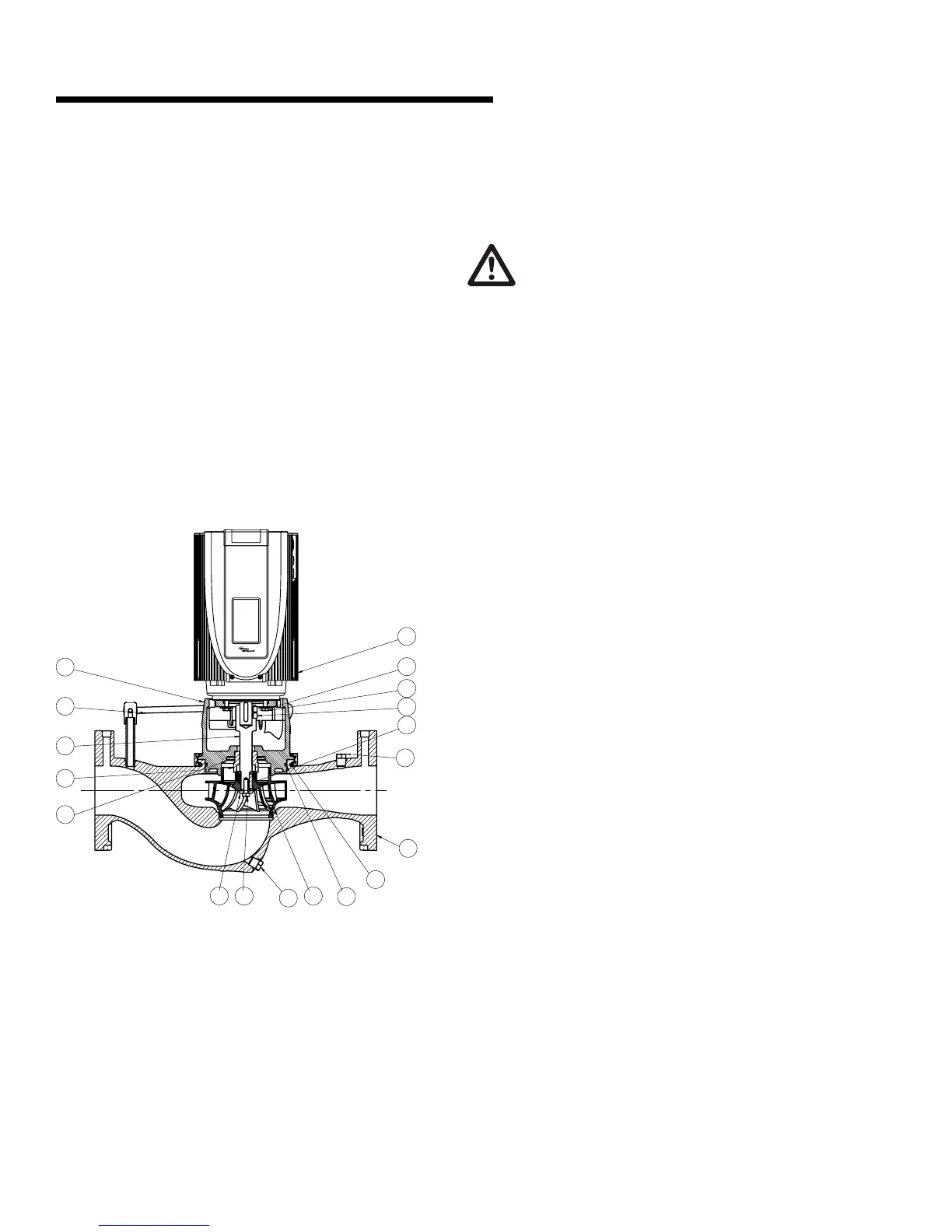
6.3.2 mechanical seal replacement instruc-
tions for close-coupled pumping units
(series 4380, 4280 & 4372)
80
101
86
83
16
36
35
94
21
40
10
43
44
59
62
102
100
61
The close-coupled or motor mounted type Vertical in-Line
pumps use vertical shaft-down ball bearing motors (integrated
motors and drives). Each pump and motor unit is pipe mounted
and as such relies on the piping only for support. The piping
support is designed for the weight of the piping, liquid, pump
and motor and other pipe fittings. The pumping unit should not
be independently secured to the building structure. If the pump
is mounted separately to any structure, the pump must be iso-
lated from the piping with flexible piping connections. For units
with larger motors it is advisable to install a permanent device
for lifting the rotating assembly out of the pipe mounted casing
to service the unit.
Breakdown procedures:
caution
Exercise extreme care when handling power wiring.
Ensure that the fuses are removed or breaker discon-
nected in the power line to the motor. Power discon-
nect should be within sight of the pump being serviced and
tagged with the reason for disconnection.
a Electrical wiring
If the pump and/or motor assembly is to be serviced on a
bench, the motor wiring must be disconnected.
b Isolation valves
If the system is not drained: Ensure that the suction and dis-
charge piping isolation valves are closed. Remove drain plug
(35) from the bottom of the casing and drain the pump.
c Prepare assembly for removal
Secure the motor (10) by lifting straps to an overhead chain
fall or similar lifting device. The device must be designed to lift
the weight of the unit safely. Raise the lifter to bring the lifting
straps taut. Disconnect the flush/vent flex hose from pump
suction and secure flex hose to one side. Remove the clamp
ring between casing (100) and adapter (40). Care should
be taken not to apply pressure to the outside diameter of the
adapter, to prevent possible breakage, outside pressure should
be on the casing only.
d Remove rotating assembly
The rotating assembly [motor, adapter and impeller] (10, 40 &
80) may now be lifted out of the casing.
e Rotating assembly notes
The impeller (80) is fastened directly to the stub shaft and
must be removed to replace the mechanical seal assembly
(61/62). This may be accomplished on a safe surface near the
installation, or more conveniently on a work bench.
f Impeller cap screw
The impeller (80) should be prevented from rotating while the
impeller cap screw (86) is loosened. A heavy screwdriver or
pry bar may be inserted in between the impeller blades to en-
able the impeller cap screw (86) to be backed o with a socket
wrench [note: be careful not to damage the impeller blades].
Remove the impeller cap screw and washer (86 & 83).
g Pump impeller
Using wheel pullers, with the jaws behind the rear shroud of
the impeller (80) [Behind a vane at each side] pull the impeller
free of the pump shaft. Impeller that is dicult to remove may
be loosened by heating the impeller hub with a torch during the
pulling process to remove the impeller from the motor shaft.