installation &
operating instructions
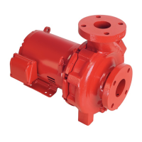
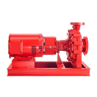
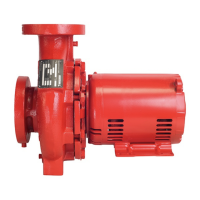
Design Envelope 4200h & 4280
End Suction Horizontal Pumping Units
41
h Remove mechanical seal from motor shaft
The mechanical seal spring usually comes free with the impel-
ler. The mechanical seal rotating element [seal head] (62)
must be pried loose with pry bars or screwdrivers, placed under
each side of the seal drive band. Leverage is applied against the
adapter. Once loosened, the seal may be pulled free of
the shaft.
Do not damage the carbon face when removing the rotating
element [seal head]. It may be needed for analysis if seal failure
investigation is required.
i Remove seal seat from adapter
The stationary seat (61) typically O-ring or L-cup mounted
Silicon Carbide material, is pried loose from the recess in the
adapter. If the seat cannot be removed in this manner, remove
the motor cap screws and washers [lock washers] (43,44)
and separate the adapter (40) from the motor (10). A screw-
driver may then be used to push the seat out of the adapter
from the rear.
j Remove old casing gasket
The former adapter O-ring should be scraped from the adapter,
leaving clean surfaces [groove] for the new O-ring. [A standard
putty knife and wire brush are useful for this purpose].
Assembly Procedures
k Replace mechanical seal
• Clean the shaft stub (21) surface, ensuring all the former
seal elastomer pieces have been removed. Inspect for dam-
age. Replace if necessary.
• Install a new stationary seat (61) in the adapter cavity, being
sure the lapped (polished) side of the insert is facing up. En-
sure that the cavity has been thoroughly cleaned. Lubricate
the stationary seat O-ring or L-cup with a small amount
silicon or glycerine lubricant and firmly press down straight
and even into the adapter cavity. Do not press the seat in
with bare fingers or hammer it down, use a clean cloth or
the cardboard disc typically supplied with the seal packag-
ing. Contamination of the polished and lapped stationary
seat face could cause leakage. If the adapter was removed
from the motor, taking care that the stationary seat is care-
fully guided over the stub shaft when assemble the adapter
back onto the motor.
• Lubricate the inside of the rotating seal [seal head] (62)
with a small amount of silicon or glycerine lubricant and
slide onto the stub shaft (21) with a twisting motion, carbon
face first, until the carbon face is pressed firmly against the
stationary seat (61). Firmly press on the rotating seal [seal
head] metal parts with a screw driver all the way around
the seal which will ensure that the faces are mated properly.
Remove the spring retainer from the seal spring and place
the seal spring over the rotating seal.
l Replace pump impeller
• Install the impeller key on the shaft and place the seal spring
retainer onto the impeller hub register. Slide the impeller in
place on the stub shaft.
• Take care and ensure that the seal spring is kept in place on
the seal rotating assembly and fits well into the retainer on
the impeller hub.
m Tighten impeller cap screw
It is good practice to replace self locking screws, once removed.
Install the impeller cap screw and washer (83 & 86). Hold
the impeller the same way as when the cap screw was success-
fully loosened (pry bar or screw driver placed carefully
between the impeller blades) and tighten the cap screw with a
socket wrench.
n Install new adapter O-ring
Insert new adapter O-ring into the O-ring groove of the adapter
and apply silicon or glycerine lubricant around the O-ring.
o Clamp Ring
Insert Clamp Ring thru the impeller and adapter flange. Tighten
the nut on the clamp ring to 90-100 lbs-in.
p Lower rotating assembly into place
The rotating assembly motor, adapter and impeller combina-
tion may now be lowered into the casing.
q Casing and adapter clamp-ring
The casing and adapter clamp-ring is now installed and tight-
ened with a wrench.
Reconnect the flush/vent flex hose assembly [check for dam-
age and replace if necessary].
r Isolation valves
Replace the casing drain plug and open the suction and dis-
charge isolation valves.
s Motor wiring
• The motor conduit and its wiring are now replaced. If the
motor is new, double check that the voltage and rpm are
identical to the original motor.
• Be sure to check rotation of the motor after rewiring if the
motor is three phase and correct if necessary, by switching
any two lead wires.
• Ensure that the pump is filled with water before operating to
check rotation.